High-power-density membrane electrode for proton exchange membrane fuel cell and preparation method thereof

A technology of proton exchange membrane and fuel cell membrane, which is applied in the direction of fuel cells, circuits, electrical components, etc., can solve the problems of low power density of fuel cell membrane electrodes and the gap between the requirements of membrane electrode power density, etc., and achieve a simple and easy preparation method , Improve battery performance, low cost effect

Active Publication Date: 2017-05-31
SOUTH CHINA UNIV OF TECH
View PDF11 Cites 34 Cited by
  • Summary
  • Abstract
  • Description
  • Claims
  • Application Information

AI Technical Summary

Problems solved by technology

[0011] Although the methods reported above have different effects in improving the performance of membrane electrodes, the power density of current fuel cell membrane electrodes is still low, which is lower than that of highly compact fuel cell systems such as electric vehicles. There is still a huge gap in requirements

Method used


Image

  • High-power-density membrane electrode for proton exchange membrane fuel cell and preparation method thereof
  • High-power-density membrane electrode for proton exchange membrane fuel cell and preparation method thereof
  • High-power-density membrane electrode for proton exchange membrane fuel cell and preparation method thereof

Examples


Embodiment 1

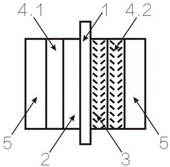
[0055] The first step is to take a 4cm×4cm Nafion211 proton exchange membrane, first place it in 5% hydrogen peroxide at 80°C for 1 hour, wash it with distilled water, and put it in 0.5mol L -1 treated in a sulfuric acid solution at 80°C for 1 hour, and then washed with distilled water. Place the treated Nafion membrane on the fixed frame of the prepared membrane electrode and fix it, the size of the active area is 5cm 2 , to prevent the membrane from shrinking and deforming during the spraying of the catalyst slurry;

[0056] In the second step, the carbon nanotubes are placed in a concentrated sulfuric acid / concentrated nitric acid solution with a volume ratio of 3:1 and ultrasonically treated for 30 minutes, refluxed at 80°C for 8 hours, filtered and washed with deionized water until the carbon nanotubes are neutral, and the obtained Acid treatment of carbon nanotubes;

[0057] The third step puts the acid-treated carbon nanotubes in the second step into a quartz tube fur...

Embodiment 2

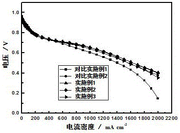
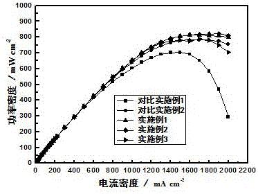
[0066] Except weighing the carbon-supported platinum catalyst, perfluorosulfonic acid polymer, carbon nitride nanotube and isopropanol by the mass ratio of 10:2.5:2:500, other steps are the same as Example 1, battery activation mode and test The method is exactly the same as Example 1. The battery polarization curve is shown in Figure 2. When the voltage is 0.7V and 0.6V, the current density can reach 700 mA cm -2 and 1300 mA cm -2 . Maximum power density of 822 mW cm -2 .

Embodiment 3

[0068] Except weighing carbon-supported platinum catalyst, perfluorosulfonic acid polymer, carbon nitride nanotube and isopropanol by mass ratio of 10:2.5:3:500, other steps are the same as Example 1, battery activation method and test The method is exactly the same as Example 1. The battery polarization curve is shown in Figure 2. When the voltage is 0.7V and 0.6V, the current density can reach 700 mA cm -2 and 1250 mA cm -2 . Maximum power density of 780 mW cm -2 .


PUM

PropertyMeasurementUnit
thicknessaaaaaaaaaa

Abstract

The invention discloses a high-power-density membrane electrode for a proton exchange membrane fuel cell and a preparation method thereof. According to the method, the thickness of solid electrolyte is reduced, the thickness of a catalyst layer is reduced by using a high-content catalyst, and a nano-carbon tube or carbon fiber is introduced into a cathode catalyst layer and / or gas diffusion layer to improve mass transfer of the catalyst layer and the diffusion layer, so that the power density of a membrane electrode is greatly improved. The preparation method is simple in steps, is practical and feasible and is low in cost, can be used for reducing the thickness of the membrane electrode while improving the performance of the membrane electrode, and is favorable to preparation of high-power-density fuel cells, galvanic piles and systems.

Description

technical field [0001] The invention relates to the field of proton exchange membrane fuel cells, in particular to a high power density membrane electrode containing hydrophilic carbon nanotubes or nitrided carbon nanotubes in a cathode catalytic layer or a cathode gas diffusion layer and a preparation method thereof. Background technique [0002] Proton exchange membrane fuel cell (PEMFC) is a new type of green energy technology. It has the advantages of high energy conversion efficiency, fast start-up at low temperature, and no pollution. It has broad application prospects in automobile power and small portable power generation equipment. The research on PEMFC has become a hot topic in the field of green energy, and many developed countries are competing to develop this technology. [0003] The membrane electrode of proton exchange membrane fuel cell is mainly composed of anode / cathode catalyst layer, anode / cathode gas diffusion layer and Nafion proton exchange membrane. ...

Claims


Application Information

Patent Timeline
Patent Type & Authority Applications(China)
IPC IPC(8): H01M8/1004
CPCH01M8/1004Y02E60/50
Inventor 廖世军侯三英池滨刘广智舒婷宋慧宇
Owner SOUTH CHINA UNIV OF TECH
Why Eureka
Try Eureka