
Apparatus for localization using image and range data and method thereof

Active Publication Date: 2011-12-08
SAMSUNG ELECTRONICS CO LTD
View PDF2 Cites 16 Cited by
  • Summary
  • Abstract
  • Description
  • Claims
  • Application Information

AI Technical Summary

Benefits of technology

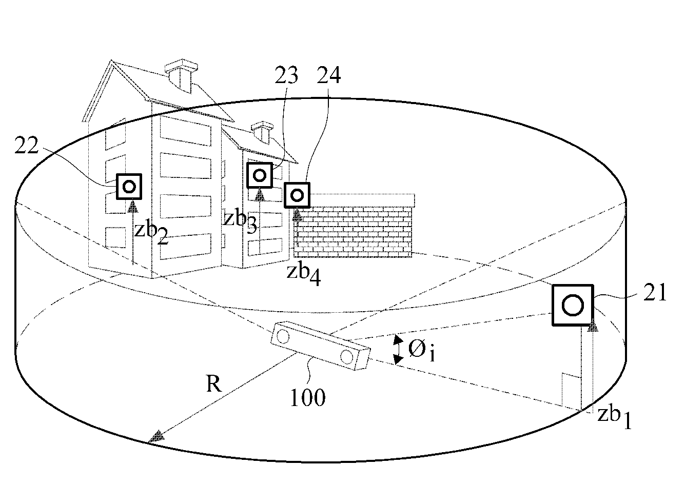
The patent describes a localization apparatus and method that can use both a BO sensor and an RO sensor simultaneously for accurate localization. The apparatus includes an image sensor to capture images, a range sensor to output range data, an image feature point information processing unit to extract image feature points and generate image feature point information, a range feature point information processing unit to generate range feature point information, and a state estimation unit to estimate the position of the localization apparatus based on the image feature point information and the range feature point information. The state estimation unit increases the uncertainty of the range feature point information based on the average height and angle of the image feature points to estimate the state variable. The apparatus can determine the uncertain part of the range feature point information and exclude it from the observation value if the uncertainty exceeds a certain threshold. The method involves obtaining image and range data, extracting image feature points, generating image feature point information, generating range feature point information, and estimating the state variable of the localization apparatus. The technical effect of this invention is to provide a more accurate and reliable localization system for various applications such as autonomous vehicles.

Problems solved by technology

When performing localization by use of the information sensed from the BO sensor, a local position can be precisely localized but a global position is less precisely localized, due to accumulated error.

Method used


Image

  • Apparatus for localization using image and range data and method thereof
  • Apparatus for localization using image and range data and method thereof
  • Apparatus for localization using image and range data and method thereof

Examples


Embodiment Construction

[0025]The following detailed description is provided to assist the reader in gaining a comprehensive understanding of the methods, apparatuses and / or systems described herein. Various changes, modifications, and equivalents of the systems, apparatuses and / or methods described herein will suggest themselves to those of ordinary skill in the art. Descriptions of well-known functions and structures are omitted to enhance clarity and conciseness. Elements, features, and structures are denoted by the same reference numerals throughout the drawings and the detailed description. The size and proportions of some elements may be exaggerated in the drawings for clarity and convenience.

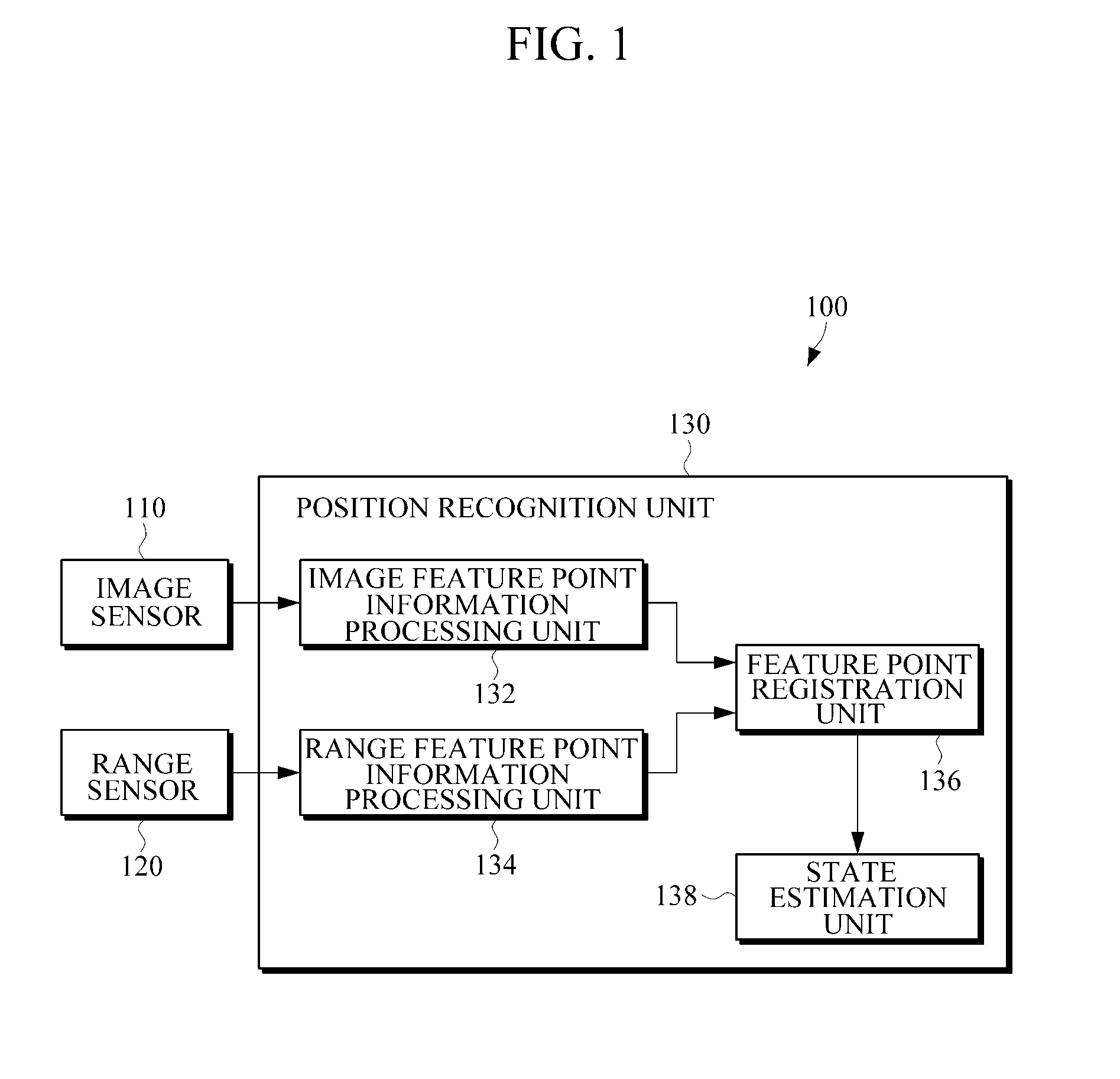
[0026]FIG. 1 is a block diagram illustrating an exemplary a localization apparatus according to an embodiment. A localization apparatus 100 includes an image sensor 110, a range sensor 120 and a position recognizing unit 130. The localization apparatus 100 may be implemented using a camera, a mobile robot and a ...


PUM


Abstract

A localization apparatus and method for localizing by use of image information and range data are provided. The localization apparatus includes an image sensor which captures an image and outputs image data, a range sensor which senses a distance and outputs a range sensing signal, an image feature point information processing unit which extracts image feature points from the sensed image and generates image feature point information about the extracted image feature points, a range feature point information processing unit which generates range feature point information about range feature points from the range sensing signal, and a state estimation unit which estimates a state variable including a position of the localization apparatus by using the image feature point information and the range feature point information as an observation value.

Description

CROSS-REFERENCE TO RELATED APPLICATION[0001]This application claims the benefit under 35 U.S.C. §119(a) of Korean Patent Application No. 10-2010-0054093, filed on Jun. 8, 2010, the disclosure of which is incorporated by reference in its entirety for all purposes.BACKGROUND[0002]1. Field[0003]The following description relates to an apparatus and method for localization, and more particularly, to an apparatus and method for localization using image information and range data.[0004]2. Description of the Related Art[0005]Simultaneous Localization And Mapping (SLAM) is an algorithm used by robots or vehicles to recognize their positions while at the same time building a map. An SLAM algorithm repeats a consecutive motion including building a map of an environment of a robot at a position (e.g., a predetermined position), and determining a new position of the robot based on the built map, thereby estimating the current position of the robot and the map of the environment of the robot. A b...

Claims


Application Information

Patent Timeline
Patent Type & Authority Applications(United States)
IPC IPC(8): G06K9/46
CPCG06K9/00664G06V20/10G06T7/97G01C11/04
Inventor CHOI, HYUN-DOPARK, JUN-HO
Owner SAMSUNG ELECTRONICS CO LTD
Learn More