Thermographic Camera and Method for the Recording and/or Modification and Reproduction of Thermal Images of a Scene and/or of an Object

a technology of thermal images and cameras, applied in the field of thermal cameras, can solve the problems of inability of human observers to resolve such fine gray gradients with certainty, higher acquisition costs and operating costs, and achieve the effect of optimal signal resolution

Inactive Publication Date: 2011-12-08
JENOPTIK OPTICAL SYST
View PDF0 Cites 9 Cited by
  • Summary
  • Abstract
  • Description
  • Claims
  • Application Information

AI Technical Summary

Benefits of technology

[0013]It is the object of the invention to show a possibility by which an optimal signal resolution can be achieved with the least possible effort at low object temperatures without signal overload at high temperatures.

Problems solved by technology

However, it is impossible for a human observer to resolve such fine gray gradients with certainty.
One disadvantage of this method is that if the cooling of the detector fails, the thermographic system is “blind.” Other drawbacks of cooled systems include the higher acquisition costs and operating costs and the occasional long start-up periods before the system has cooled the detector down to operating temperature.
Systems of this kind make do without expensive, cumbersome cooling devices.
However, they deliver comparatively poorer results.
However, a linear signal display requires a compromise between resolution and dynamics.
With a steep characteristic, cold objects are capable of good thermal resolution, but high object temperatures quickly lead to saturation.
Conversely, with a flat characteristic that is optimized for high temperatures, details can no longer be perceived.

Method used


Image

  • Thermographic Camera and Method for the Recording and/or Modification and Reproduction of Thermal Images of a Scene and/or of an Object
  • Thermographic Camera and Method for the Recording and/or Modification and Reproduction of Thermal Images of a Scene and/or of an Object
  • Thermographic Camera and Method for the Recording and/or Modification and Reproduction of Thermal Images of a Scene and/or of an Object

Examples


Embodiment Construction

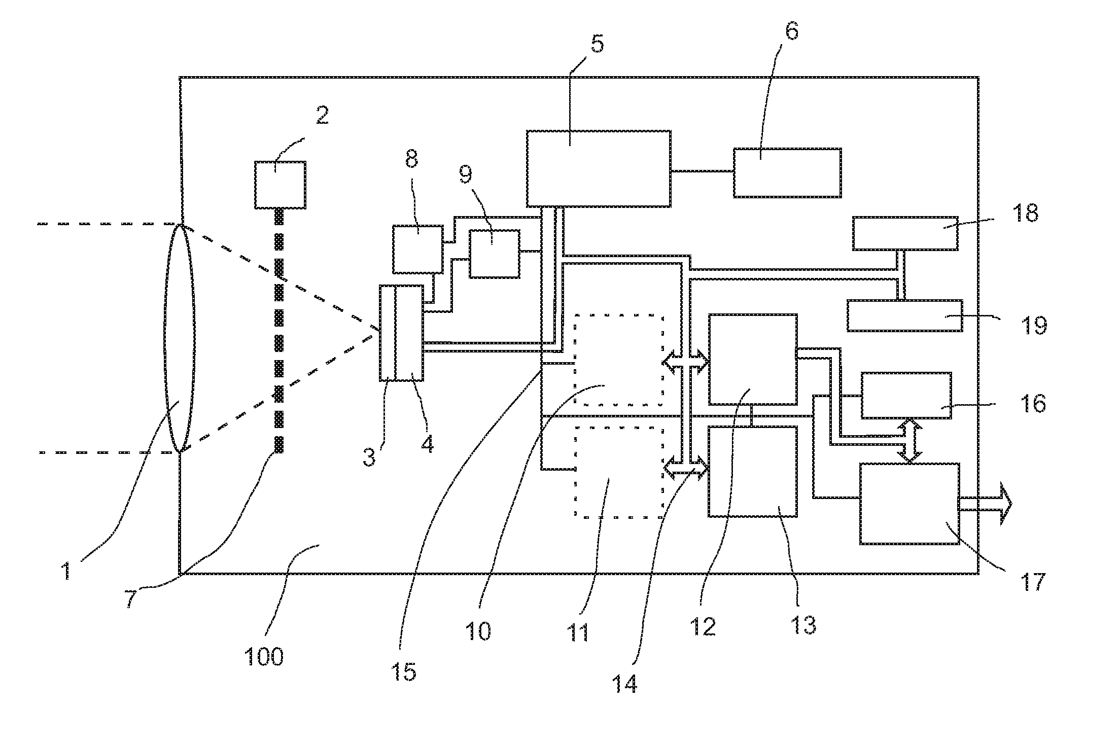
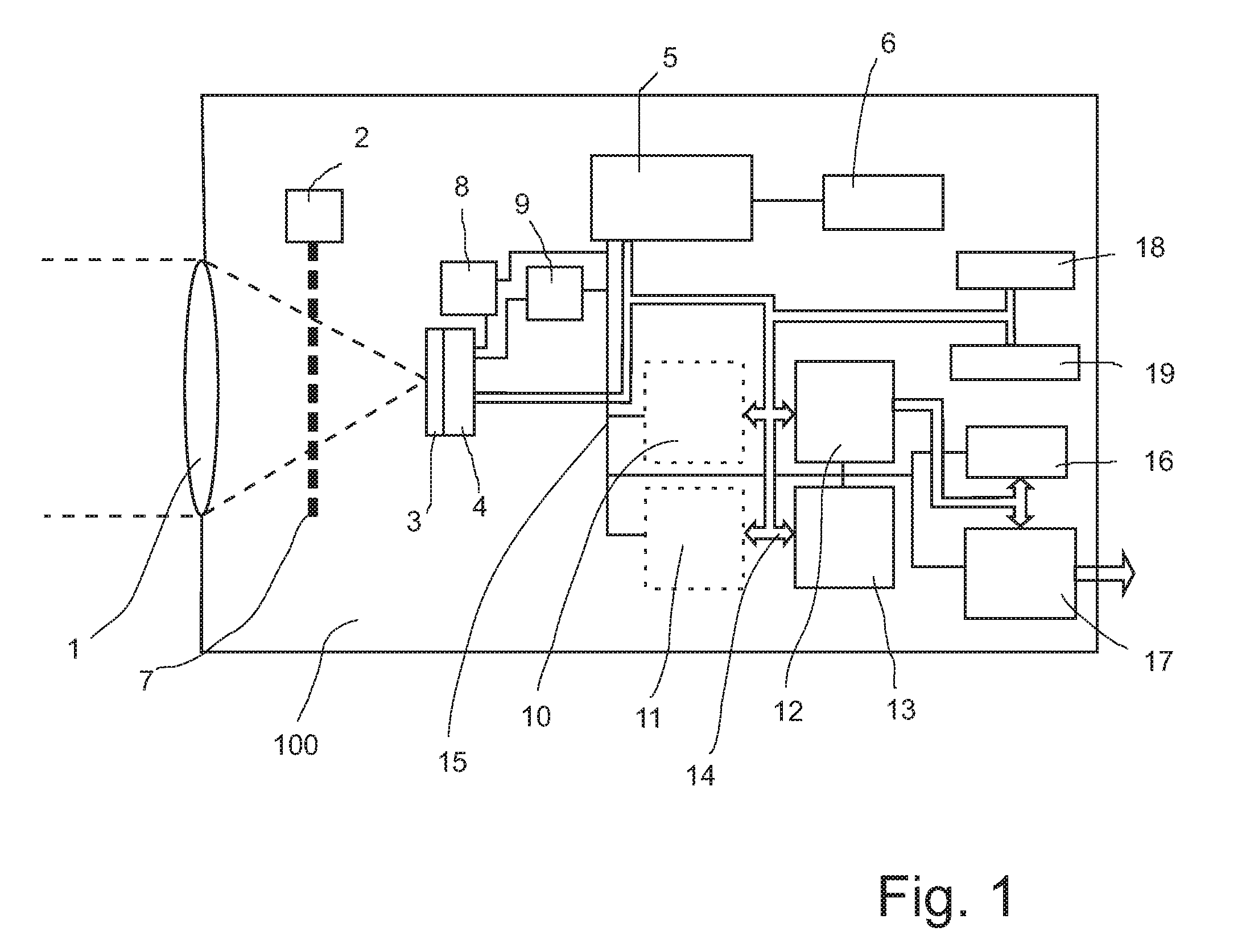
[0037]FIG. 1 shows a thermographic camera 100 with its essential components comprising IR optics 1, shutter control device 2, microbolometer FPA (focal plane array) 3, readout unit 4, and processor unit 5.

[0038]The IR optics 7 project an infrared image on the microbolometer FPA (focal plane array) 3. The microbolometers are generally arranged in matrix shape. However, as was already mentioned above, other arrangements are also conceivable. The processor unit 5 controls the microbolometer FPA 3 in a clock pulse given by the clock control 6 for recording frames in a corresponding manner. Further, the processor unit 5 controls the shutter control device 2 in a shutter clock that can be given as an adjustable parameter to swivel the shutter 7 into or out of the beam path so that dark images and thermal images are generated alternately in a determined sequence.

[0039]When the shutter 7 is swiveled in, this means that the beam path is interrupted and the microbolometer FPA 3 receives only ...


PUM


Abstract

The present invention is directed to a thermographic camera and to a method for generating thermal images with this thermographic camera as is described generically in DE 698 30 731 T2. The object of the invention is to provided a possibility for achieving an optimal signal resolution at low object temperatures in an economical manner without signal overload at high temperatures. This object is met by a method for the recording and reproduction of thermal images of a scene and/or of an object, comprising the following steps: a pixel-based thermal image frame is generated by means of IR optics and a pixel-based detector unit; a dark image is generated for implementing a non-uniformity correction (NUC) to eliminate non-uniformities arising from the detector and/or disturbance sources in the optical beam path; the existing pixel-based thermal image frame is corrected by weighting the individual pixel signals with a nonlinear characteristic line which is generated and stored beforehand for generating a corrected output thermal image; and finally, the corrected output thermal image is supplied to a display unit or to an interface for external equipment.

Description

RELATED APPLICATIONS[0001]This application claims priority to German Patent Application No. DE 10 2010 023 170.3, filed Jun. 7, 2010, which is incorporated herein by reference in its entirety.FIELD OF THE INVENTION[0002]The present invention is directed to a thermographic camera and a method for producing thermal images with a thermographic camera such as is described generically in DE 698 30 731 T2.BACKGROUND OF THE INVENTION[0003]Thermography is an imaging method which renders visible the thermal radiation (mid-infrared to far infrared) of an object or body that is not visible to the human eye. In thermography, temperature distributions on surfaces and objects are acquired and displayed. Thermography is a non-contact measurement method.[0004]Images that are generated by infrared cameras are initially gray scale. Current camera models are capable of displaying up to 256 (8 bit) gradients of gray. However, it is impossible for a human observer to resolve such fine gray gradients wit...

Claims


Application Information

Patent Timeline
Patent Type & Authority Applications(United States)
IPC IPC(8): H04N5/33H04N5/77
CPCH04N5/243H04N5/33G06T2207/10048H04N5/3655G06T5/008H04N5/3651H04N23/76H04N25/673H04N25/671
Inventor WEISBACH, FRANK
Owner JENOPTIK OPTICAL SYST
Why Eureka
Try Eureka