Temperature controlled battery pack assembly and methods for using the same

a battery pack and temperature control technology, applied in the field of batteries, can solve the problems of adversely affecting the battery life of datacenters, reducing the effective service life of batteries,

Inactive Publication Date: 2011-12-08
EATON CORP
View PDF3 Cites 31 Cited by
  • Summary
  • Abstract
  • Description
  • Claims
  • Application Information

AI Technical Summary

Benefits of technology

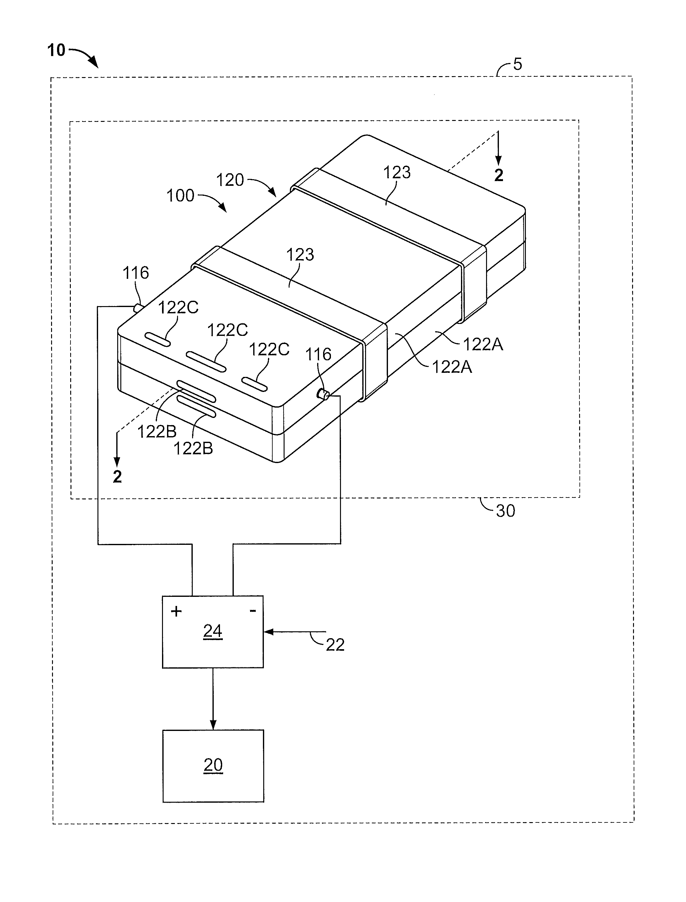
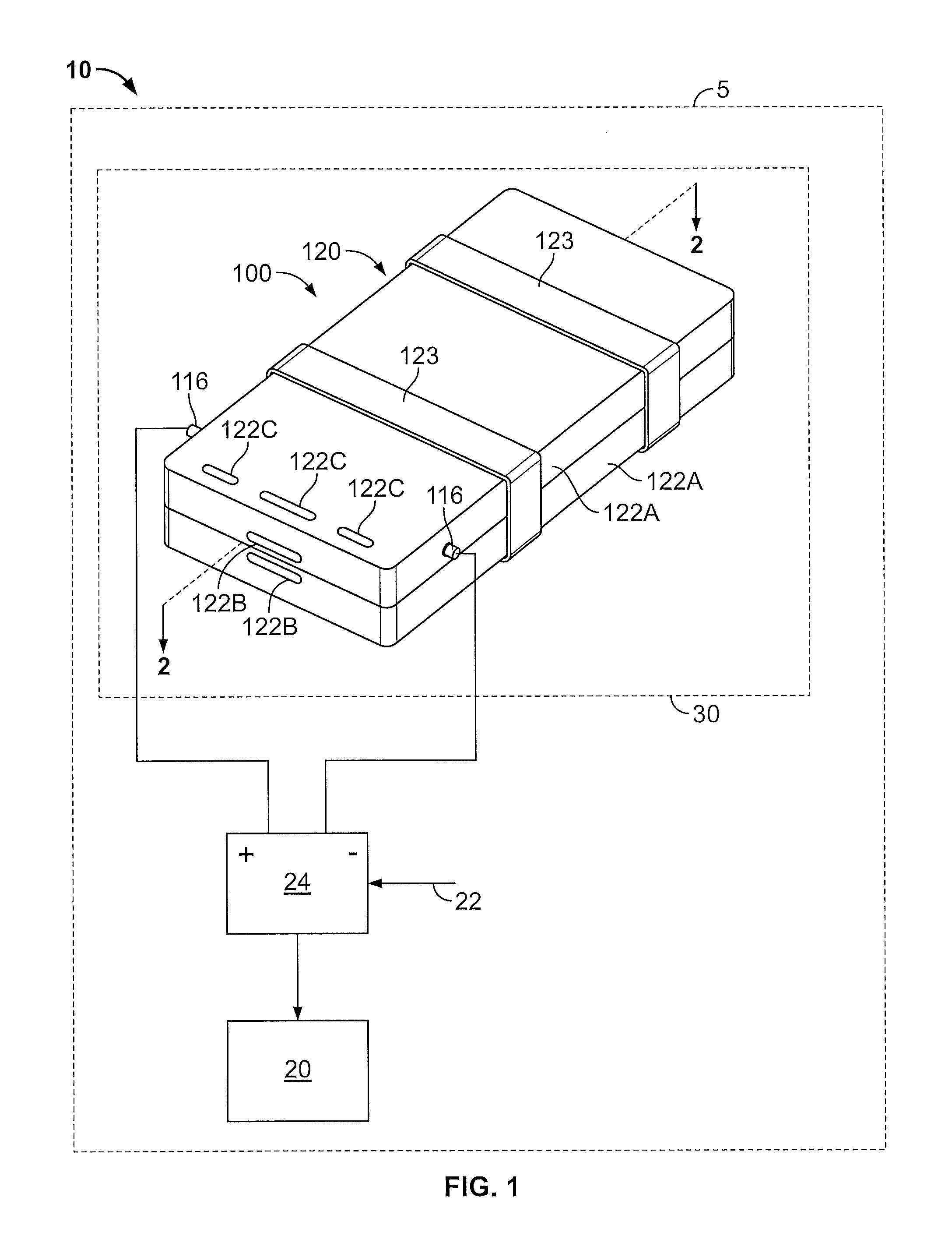
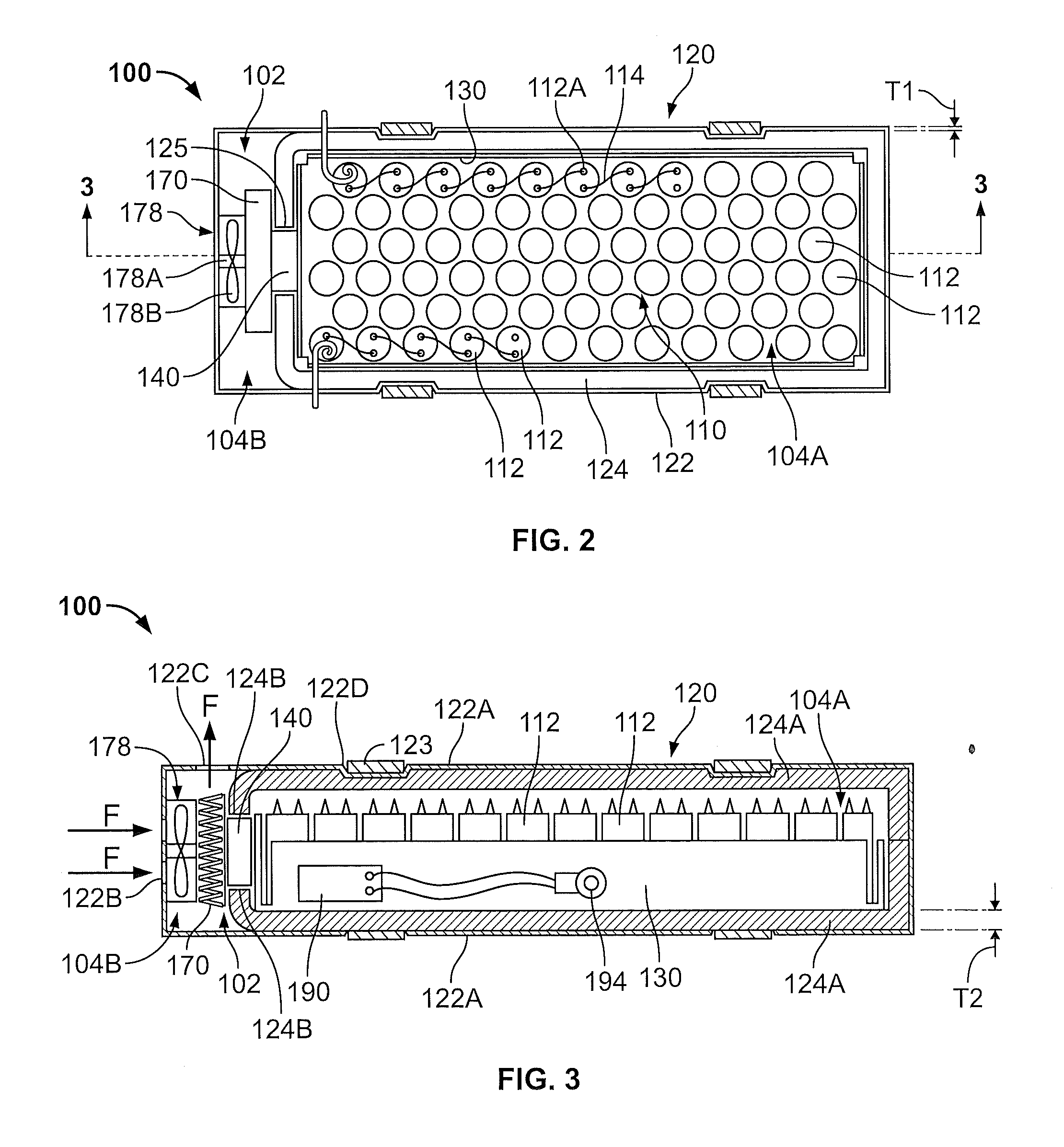
[0005]According to some embodiments, the thermoelectric cooler device is operable to actively transfer heat from the inner surface to the outer surface using the Peltier effect to thereby cool the at least one battery cell.

Problems solved by technology

Exposure to elevated temperatures can significantly reduce the effective service life of batteries, such as batteries used to provide emergency backup or auxiliary power to electronic equipment that enables critical functions (e.g., computer systems, telecommunications systems and medical equipment).
As a result, a continued rise in datacenter temperatures may adversely impact battery life in datacenters.

Method used


Image

  • Temperature controlled battery pack assembly and methods for using the same
  • Temperature controlled battery pack assembly and methods for using the same
  • Temperature controlled battery pack assembly and methods for using the same

Examples


Embodiment Construction

[0030]The present invention now will be described more fully hereinafter with reference to the accompanying drawings, in which illustrative embodiments of the invention are shown. In the drawings, the relative sizes of regions or features may be exaggerated for clarity. This invention may, however, be embodied in many different forms and should not be construed as limited to the embodiments set forth herein; rather, these embodiments are provided so that this disclosure will be thorough and complete, and will fully convey the scope of the invention to those skilled in the art.

[0031]It will be understood that when an element is referred to as being “coupled” or “connected” to another element, it can be directly coupled or connected to the other element or intervening elements may also be present. In contrast, when an element is referred to as being “directly coupled” or “directly connected” to another element, there are no intervening elements present. Like numbers refer to like elem...


PUM

PropertyMeasurementUnit
temperatureaaaaaaaaaa
thickness T1aaaaaaaaaa

Abstract

A temperature controlled battery pack assembly includes a housing defining a battery chamber and including thermal insulation surrounding at least a portion of the battery chamber. At least one battery cell is contained in the battery chamber. The thermal insulation inhibits thermal transfer between the at least one battery cell and the surrounding environment. A thermal bridge conductor is disposed in the battery chamber and engages the at least one battery cell. The battery pack assembly further includes a thermoelectric cooler device having an inner surface and an outer surface. The thermoelectric cooler device is operable to actively transfer heat between the inner and outer surfaces using the Peltier effect. A heat sink device is in contact with or connected to the outer surface to enable thermal conduction between the outer surface and the heat sink device. The battery pack assembly includes a fan operable to force a flow of a heat transfer fluid across the heat sink device and into the environment to enable convective heat transfer between the heat sink device and the environment. The thermal bridge conductor is in contact with or connected to the inner surface to enable thermal conduction between the inner surface and the thermal bridge conductor.

Description

FIELD OF THE INVENTION[0001]The present invention relates to batteries and, more particularly, to temperature controlled battery pack assemblies.BACKGROUND OF THE INVENTION[0002]Exposure to elevated temperatures can significantly reduce the effective service life of batteries, such as batteries used to provide emergency backup or auxiliary power to electronic equipment that enables critical functions (e.g., computer systems, telecommunications systems and medical equipment). Information technology (IT) equipment is commonly housed in a controlled datacenter environment. While the datacenter environment has traditionally been a relatively cool environment by design, there is a trend toward higher datacenter temperatures in an effort to reduce cooling requirements and improve operating efficiency. This trend is enabled by IT equipment that is more tolerant to higher temperatures. Also, there is a shift to shorter backup times as datacenters migrate to cloud computing environments. The...

Claims


Application Information

Patent Timeline
Patent Type & Authority Applications(United States)
IPC IPC(8): H01M10/50H01L35/34
CPCH01M10/5004H01M10/5018H01M10/5022H01M10/5046H01M10/5087H01M10/5067H01M10/5073H01M10/5085H01M10/5053H01M10/613H01M10/627H01M10/633H01M10/6551H01M10/6554H01M10/6563H01M10/6566H01M10/6572H01M10/658Y02E60/10
Inventor JOHNSON, JR., ROBERT WILLIAM
Owner EATON CORP
Why Eureka
Try Eureka