
Eureka
For R&D, Eureka makes reading and utilizing patents & technical documents easy.
Eureka AIR
Designed for self-driven R&D workflows. Generate viable solutions, solve complex R&D challenges, empower your innovation with AI.

Eureka Materials
Designed for material experts only. Revolutionize your material R&D, from search, analyze, to developing new materials.

TechResearch
Generate reliable direction feasibility study reports for your R&D in just a few steps.

TechSeek
Discover and master advanced knowledge NOW. Basics, ideas, possibilities, all at once.

TechMind
As an expert in R&D Theories, TechMind can generates customized viable solutions instantly.

TechRisk
Analyze your overall solution with one click, know your potential R&D risks in advance.

TechMonitor
Get weekly tech updates, stay abreast of the latest tech innovations and key insights.
Control device for legged mobile robot
- Summary
- Abstract
- Description
- Claims
- Application Information
AI Technical Summary
Benefits of technology
Problems solved by technology
Method used
Image

Examples
first embodiment
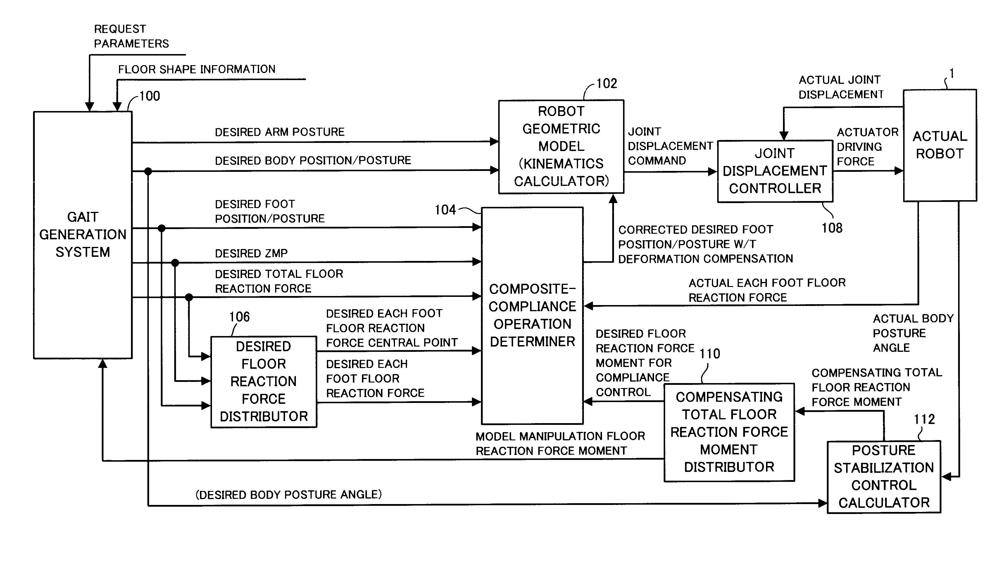
[0094]Hereinafter, a first embodiment of the present invention will be described by taking a bipedal mobile robot as an example of the legged mobile robot.
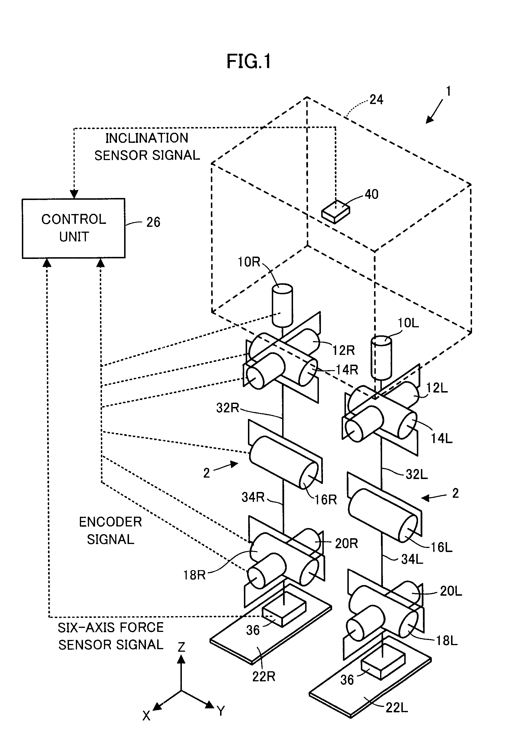
[0095]Referring to FIG. 1, a bipedal mobile robot 1 (hereinafter, simply referred to as the “robot 1”) of the present embodiment includes a body 24 as a base body, and a pair of right and left legs 2, 2, extended from the body 24 as a moving mechanism for causing the body 24 to move on a floor surface.
[0096]The body 24 is connected to the proximal end portions (upper end portions) of the legs 2, 2 through waist joints (hip joints), which will be described later, so as to be supported above the floor surface by one or both of the legs 2, 2 in contact with the floor.
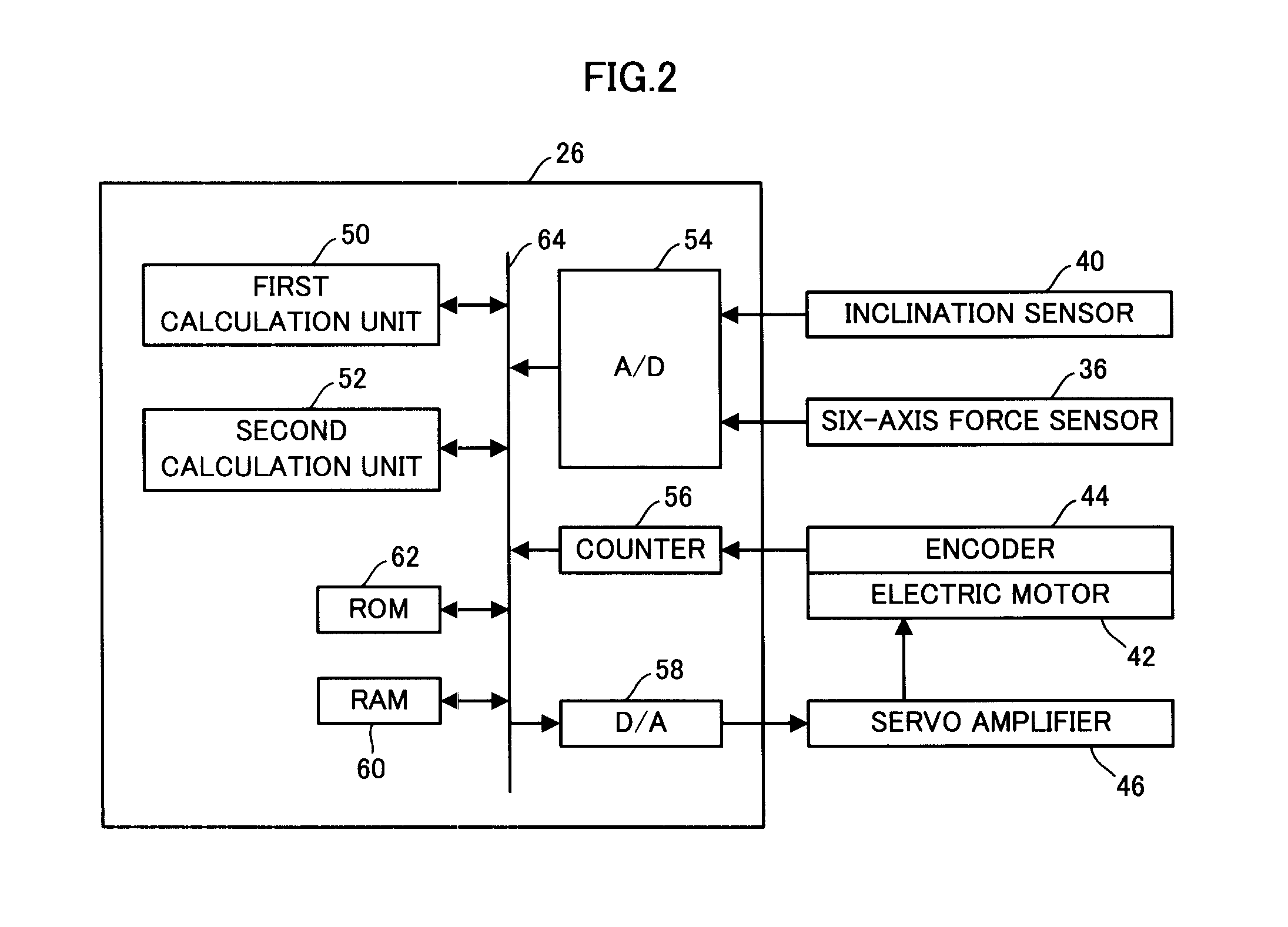
[0097]The legs 2, 2 share the same construction, each having six joints. The six joints are, in order from the body 24 side, a joint 10R or 10L for turning the waist (hip) (for rotation in a yaw direction relative to the body 24), a joint 12R or 12L for turning the waist...
second embodiment
[0575]In the above-described embodiment, in the processing in S020, as the permissible regions for restricting the desired landing position of the free leg foot 22, two permissible regions of the first landing permissible region corresponding to the geometric leg motion requisite condition and the second landing permissible region corresponding to the motion continuity requisite condition and the ZMP existence region requisite condition (the floor reaction force element permissible range requisite condition) have been used on the premise that the floor surface is a surface on which the free leg foot 22 can be landed at any place.
[0576]However, in the case where the position on which the free leg foot 22 can land is restricted dependent on the environment surrounding the robot 1 (for example, in the case where the floor surface is made up of stepping stones, in the case where there are irregularities, steps, or obstacles on the floor surface on which it is not preferable for the foot...
PUM
 Abstract
Description
Claims
Application Information
 - R&D Engineer
- R&D Manager
- IP Professional
- Industry Leading Data Capabilities
- Powerful AI technology
- Patent DNA Extraction
Browse by: Latest US Patents, China's latest patents, Technical Efficacy Thesaurus, Application Domain, Technology Topic, Popular Technical Reports.
© 2024 PatSnap. All rights reserved.Legal|Privacy policy|Modern Slavery Act Transparency Statement|Sitemap|About US| Contact US: help@patsnap.com