
Managing an energy transfer between a vehicle and an energy transfer system

a technology of energy transfer system and vehicle, applied in the direction of mechanical power/torque control, electric devices, ratio control, etc., can solve the problems of inconvenient and inefficient charging solutions of conventional automobiles

Inactive Publication Date: 2011-12-08
FAILING BRYAN MARC
View PDF2 Cites 449 Cited by
  • Summary
  • Abstract
  • Description
  • Claims
  • Application Information

AI Technical Summary

Benefits of technology

[0004]Accordingly, a need exists for a more convenient way to charge a vehicle. A need also exists for a more efficient way to charge a vehicle. Embodiments of the present invention provide novel solutions to these needs and others as described below.

Problems solved by technology

As such, conventional solutions for charging automobiles are inconvenient and inefficient.

Method used


Image

  • Managing an energy transfer between a vehicle and an energy transfer system
  • Managing an energy transfer between a vehicle and an energy transfer system
  • Managing an energy transfer between a vehicle and an energy transfer system

Examples


Embodiment Construction

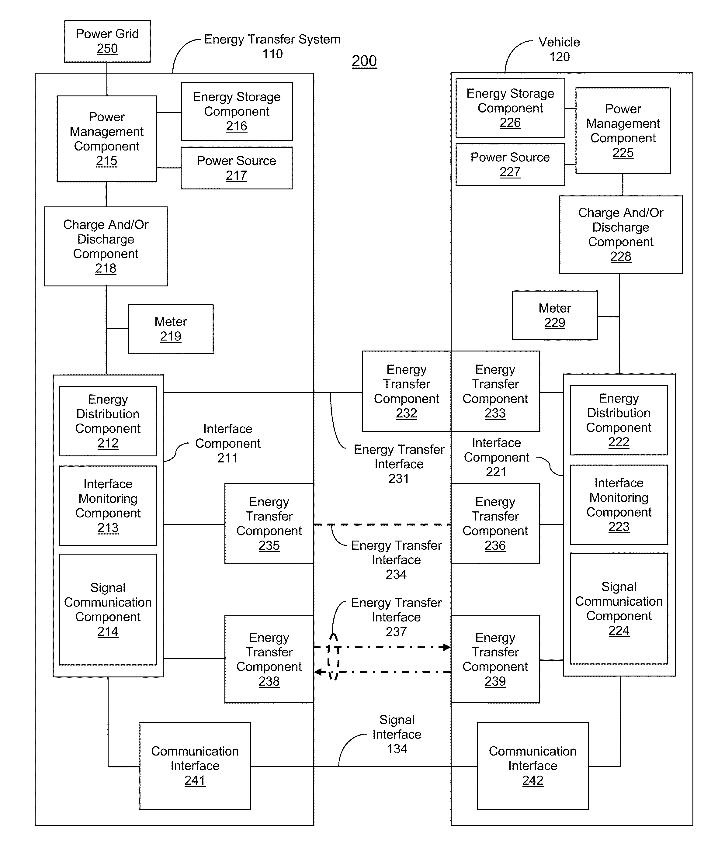
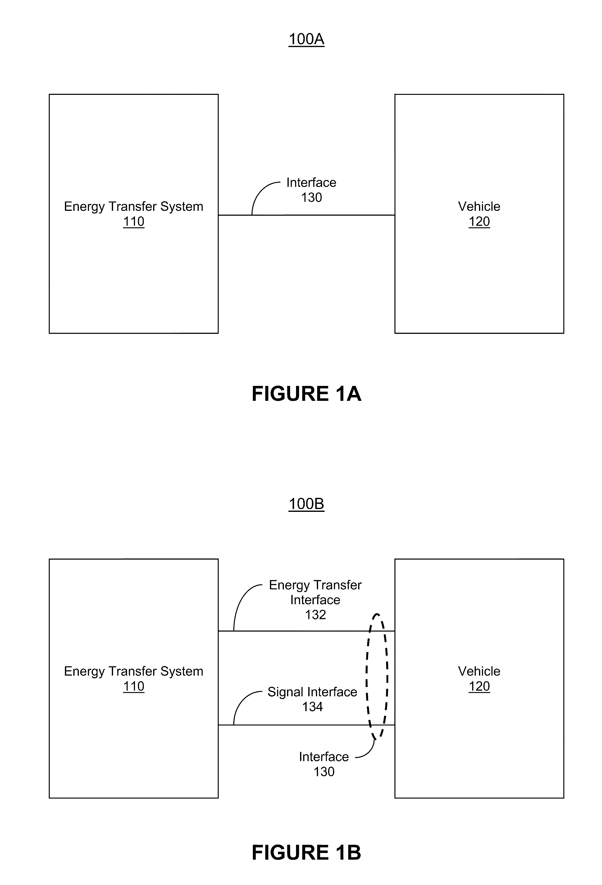
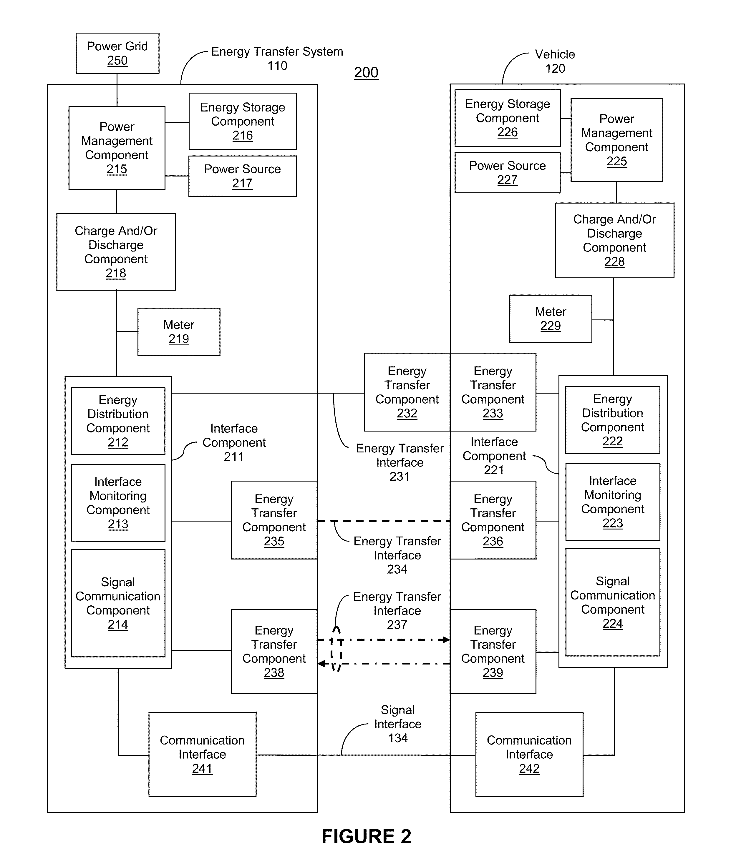
[0057]Reference will now be made in detail to embodiments of the present invention, examples of which are illustrated in the accompanying drawings. While the present invention will be discussed in conjunction with the following embodiments, it will be understood that they are not intended to limit the present invention to these embodiments alone. On the contrary, the present invention is intended to cover alternatives, modifications, and equivalents which may be included with the spirit and scope of the present invention as defined by the appended claims. Furthermore, in the following detailed description of the present invention, numerous specific details are set forth in order to provide a thorough understanding of the present invention. However, embodiments of the present invention may be practiced without these specific details. In other instances, well-known methods, procedures, components, and circuits have not been described in detail so as not to unnecessarily obscure aspect...


PUM


Abstract

A method, computer-readable medium, and system for managing a transfer of energy is disclosed.

Description

RELATED APPLICATIONS[0001]The present application is related to U.S. patent application Ser. No. ______, filed Jan. 28, 2011, entitled “IMPROVING ENERGY TRANSFER WITH VEHICLES,” naming Bryan Marc Failing as the inventor, which claims the benefit of U.S. Provisional Patent Application No. 61 / 350,771, filed Jun. 2, 2010, entitled “MANAGING A TRANSFER OF ENERGY AND INCREASING VEHICLE SECURITY.” Those applications are incorporated herein by reference in their entirety and for all purposes.[0002]The present application is related to U.S. patent application Ser. No. ______, filed Jan. 28, 2011, entitled “INCREASING VEHICLE SECURITY,” naming Bryan Marc Failing as the inventor, which claims the benefit of U.S. Provisional Patent Application No. 61 / 350,771, filed Jun. 2, 2010, entitled “MANAGING A TRANSFER OF ENERGY AND INCREASING VEHICLE SECURITY.” Those applications are incorporated herein by reference in their entirety and for all purposes.BACKGROUND OF THE INVENTION[0003]Conventional sol...

Claims


Application Information

Patent Timeline
Patent Type & Authority Applications(United States)
IPC IPC(8): G06Q40/00G06F1/26
CPCB60L3/00Y04S30/14B60L11/1842G06Q20/10H02J3/008H02J3/32H02J3/381H02J5/005Y02T10/7088Y02T10/7005Y02T90/163Y02T90/14Y02T90/128Y04S10/126Y02E60/721B60L2200/26Y02T90/169Y02T90/121B60L11/1838Y02T10/7072B60L55/00H02J2310/48H02J50/90H02J3/322H02J7/00034H02J7/00045B60L53/305B60L58/22B60L53/67B60L53/124B60L53/66B60L53/68B60L53/126Y02E60/00Y02T90/12Y02T10/70Y02T90/167Y02T90/16H02J50/10H02J50/70H02J5/00H02J50/80B60L53/60H02J50/12B60L53/12B60L58/26B60C23/041G06Q20/145
Inventor FAILING, BRYAN MARC
Owner FAILING BRYAN MARC
Learn More