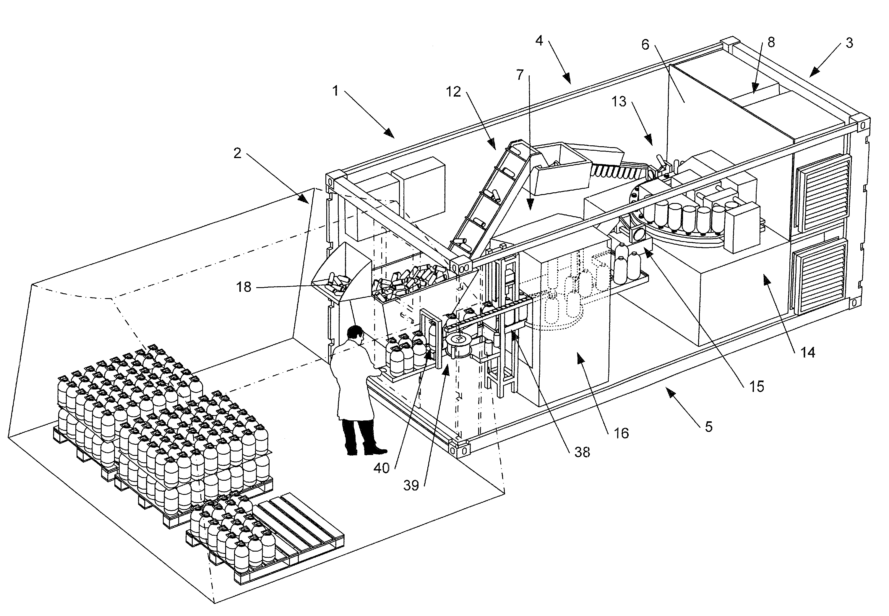
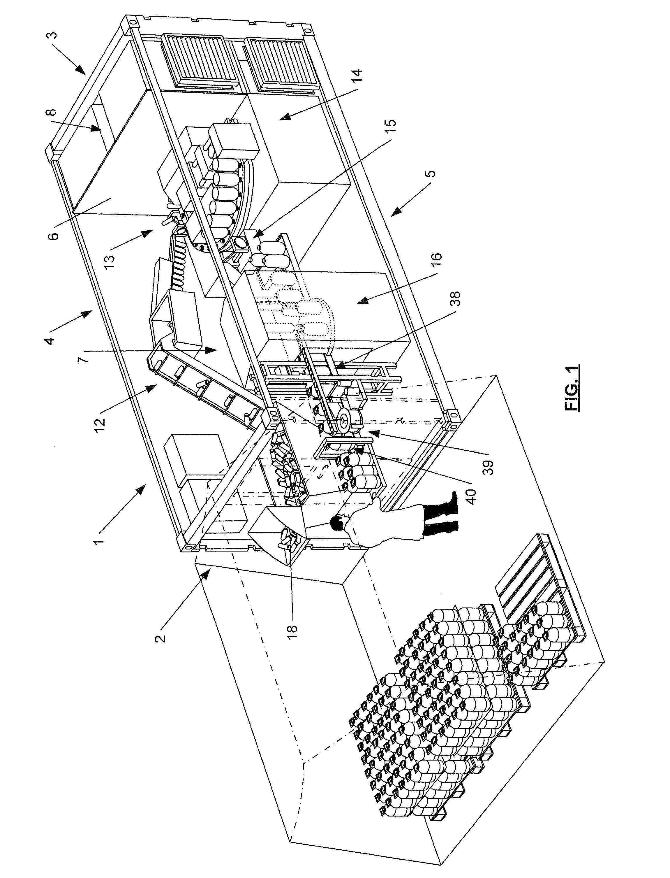
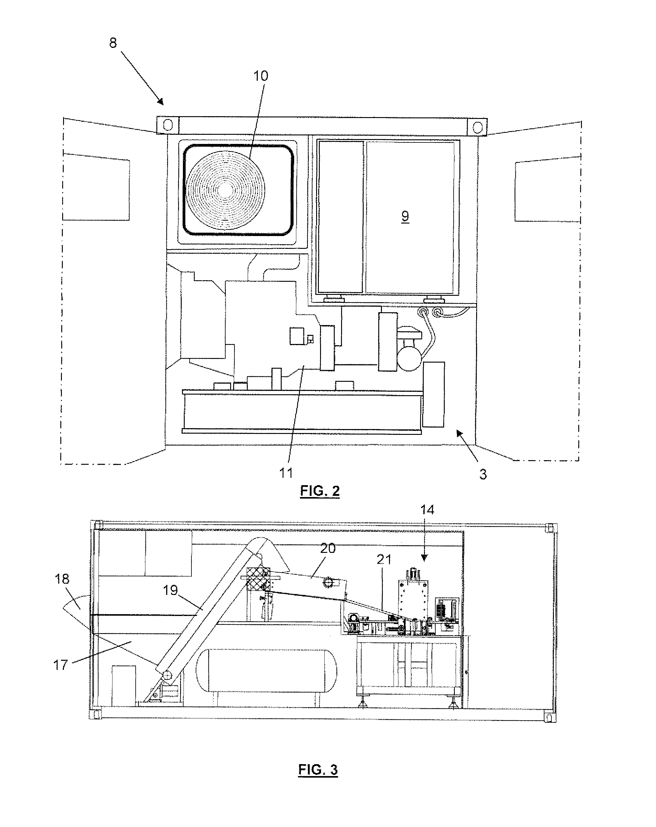
Transportable bottling plant in a container

Inactive Publication Date: 2011-12-15
CONTENO
View PDF18 Cites 35 Cited by
  • Summary
  • Abstract
  • Description
  • Claims
  • Application Information

AI Technical Summary

Benefits of technology

[0020]In preferred embodiments, the filling and closing unit comprises liquid infeed and outfeed ducts connected to liquid infeed and outfeed connectors which are provided in one of the sides of the container, so that they are accessible from outside the bottling room. The liquid infeed connector is provided for feeding the liquid with which the bottles are to be filled. The liquid infeed and outfeet connectors together can also be used to create a closed loop for a cleaning product. So by means of the liquid infeed and outfeed connectors accessible from outside the bottling room, both the liquid supply during operation and the supply and discharge of cleaning product during cleaning can be effected from outside the bottling room. This has the advantage that hygiene can be enhanced, as the risk of contamination by operators entering the bottling room is minimised in view of the fact that there is no need for an operator to enter the bottling room for the supply of either the liquid with which the bottles are to be filled or the cleaning product.
[0021]In preferred embodiments, the filling and closing unit comprises a system for treatment of the liquid with chemicals before filling the bottles, the liquid treatment system comprising a chemicals supply duct connected to a chemicals infeed connection provided in one of the sides of the container, so that it is accessible from outside the bottling room. So by means of the chemicals infeed connection accessible from outside the bottling room, the supply of chemicals for the treatment of the liquid in the liquid treatment system can be effected from outside the bottling room. This has the advantage that hygiene can be enhanced, as the risk of contamination by operators en

Problems solved by technology

The known stationary bottling plants descr

Method used


Image

  • Transportable bottling plant in a container
  • Transportable bottling plant in a container
  • Transportable bottling plant in a container

Examples


Embodiment Construction

[0035]The present invention will be described in the following with respect to particular embodiments and with reference to certain drawings but the invention is not limited thereto but only by the claims. The drawings described are only schematic and are non-limiting. In the drawings, the size of some of the elements may be exaggerated and not drawn on scale for illustrative purposes. The dimensions and the relative dimensions do not necessarily correspond to actual reductions to practice of the invention.

[0036]Furthermore, the terms first, second, third and the like in the description and in the claims, are used for distinguishing between similar elements and not necessarily for describing a sequential or chronological order. The terms are interchangeable under appropriate circumstances and the embodiments of the invention can operate in other sequences than described or illustrated herein.

[0037]Moreover, the terms top, bottom, over, under and the like in the description and the c...


PUM

PropertyMeasurementUnit
Lengthaaaaaaaaaa
Pressureaaaaaaaaaa
Acoustic propertiesaaaaaaaaaa

Abstract

The invention provides a transportable bottling plant integrated into a container. The container has a separation wall dividing the container into a bottling room and a technical room. A preform feeder, a bottle blowing unit, a filling and closing unit and first and second transferring devices are mounted in the bottling room. A power generator, an air compressor and an air conditioning unit are mounted in the technical room. The preform feeder comprises a recipient for receiving plastic bottle preforms and an ordering unit for ordering the preforms and feeding them towards the bottle blowing unit. The first transferring device is provided for transferring the preforms from the preform feeder to the bottle blowing unit. The bottle blowing unit comprises a heater for heating the preforms and a blow-moulder for blow-moulding the preforms into bottles. The second transferring device is provided for transferring the bottles from the bottle blowing unit to the filling and closing unit. The filling and closing unit comprises a filling unit for filling the bottles with a liquid and a closing unit for closing the bottles with caps.

Description

TECHNICAL FIELD[0001]The present invention relates to a transportable bottling plant in a container.BACKGROUND ART[0002]Generally, a stationary bottling plant as known in the art comprises a preform feeder, which receives plastic bottle preforms and orders them for feeding to a bottle blowing unit, which in turn applies heat and air pressure to form bottles from the preforms, and a filling and closing unit for filling the bottles with a liquid, closing them with a cap and possibly also applying a handle, a label and a code identifying lot number and date. Between these units, transferring devices are used to transfer the preforms from the preform feeder to the bottle blowing unit and to transfer the bottles from the bottle blowing unit to the filling and closing unit.[0003]Known bottling plants are stationary plants. In certain places in the world there is a need for quickly setting up a bottling plant. The known stationary bottling plants described above are not suited for this pur...

Claims


Application Information

Patent Timeline
IPC IPC(8): B65B63/08B65B3/02
CPCB67C2003/227B67C3/008B29C49/006
Inventor VAN STEEN, CHRISTOPHE ARMAND
Owner CONTENO
Why Eureka
Try Eureka