
Method of remote active testing of a device or network

a technology of remote active testing and network, applied in the field of network and communication technology, can solve the problems of increasing the complexity of the device, increasing the time and resources required for manufacturing the test device, and increasing the size and processing time of the devi

Active Publication Date: 2011-12-15
VIAVI SOLUTIONS INC
View PDF18 Cites 54 Cited by
  • Summary
  • Abstract
  • Description
  • Claims
  • Application Information

AI Technical Summary

Problems solved by technology

This increases the complexity of the devices, which may undesirably increase their size and processing time.
Further, such complexity increases the time and resources required for manufacturing the test devices.
The updates or even replacement of the test devices are inconvenient and associated with cost.
Thus conventional devices used for active testing such as network analyzers, should be constantly moved which is inconvenient and costly, or be attached at multiple locations on a network, which may be cost prohibitive considering the complexity of the devices used for active testing of multiple protocols.

Method used


Image

  • Method of remote active testing of a device or network
  • Method of remote active testing of a device or network
  • Method of remote active testing of a device or network

Examples


Embodiment Construction

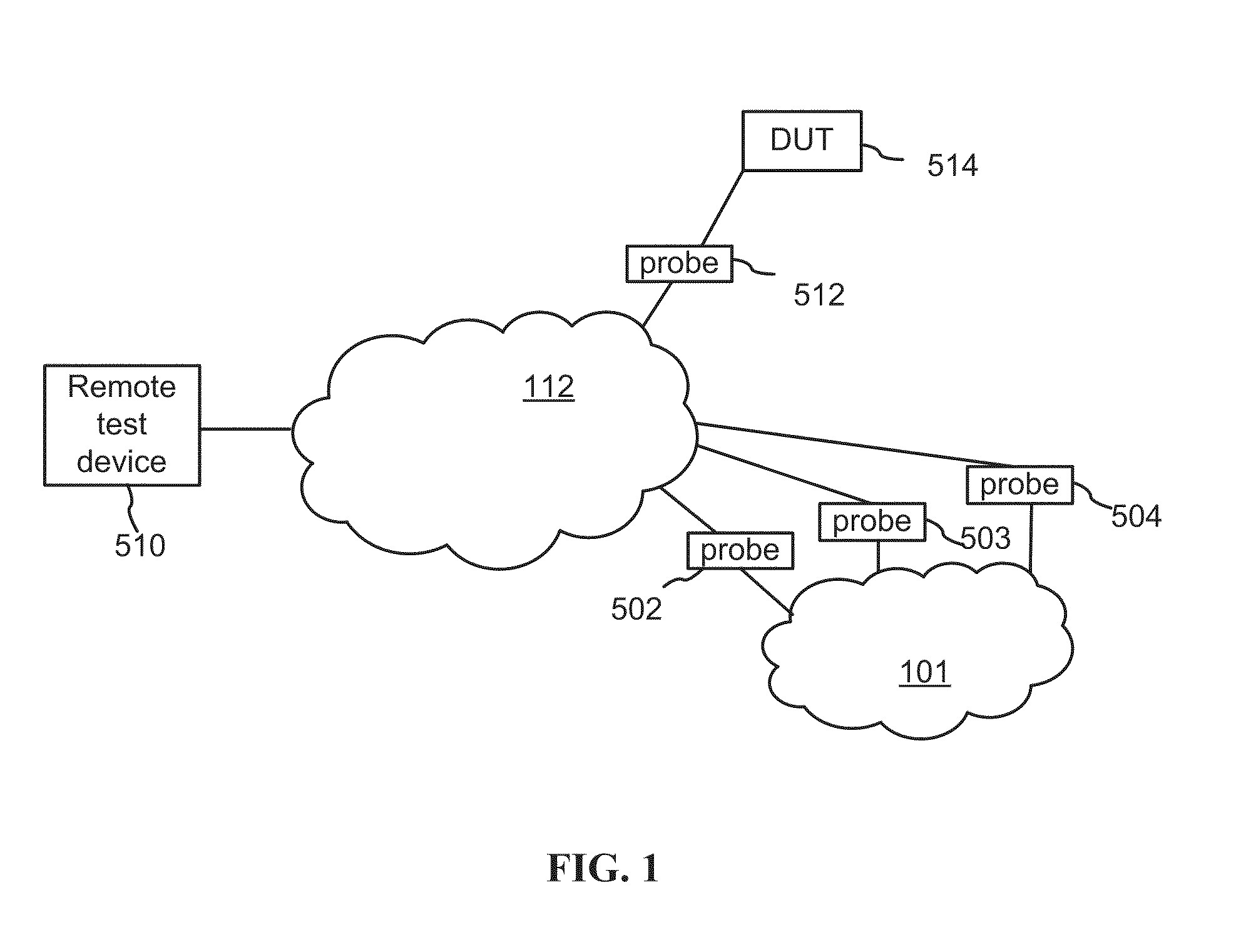
[0033]With reference to FIG. 1, a test system includes a remote test system 510 and one or more local test devices such as a probe 512 or probes 502 through 504; the remote test system 510 is in communication with the local devices test over a transport network 112 which may be any kind of a packet network. The probes 512 and 502 through 504 may be interchangeable. In the system shown in FIG. 1 the probes differ in their use: the probe 512 is connected to a communication device under test (DUT) 514; the probes 502 through 504 are connected to a network under test 101.

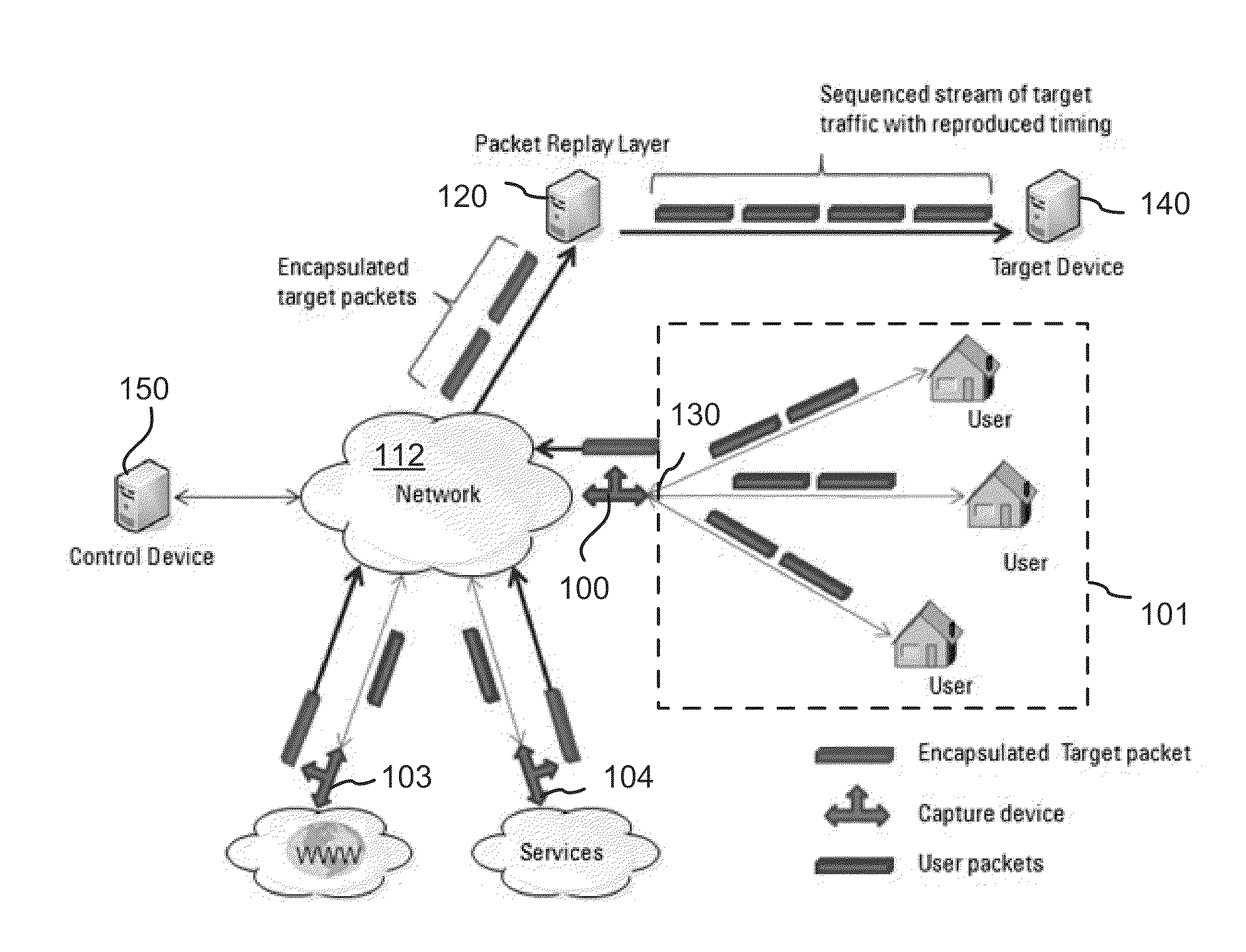
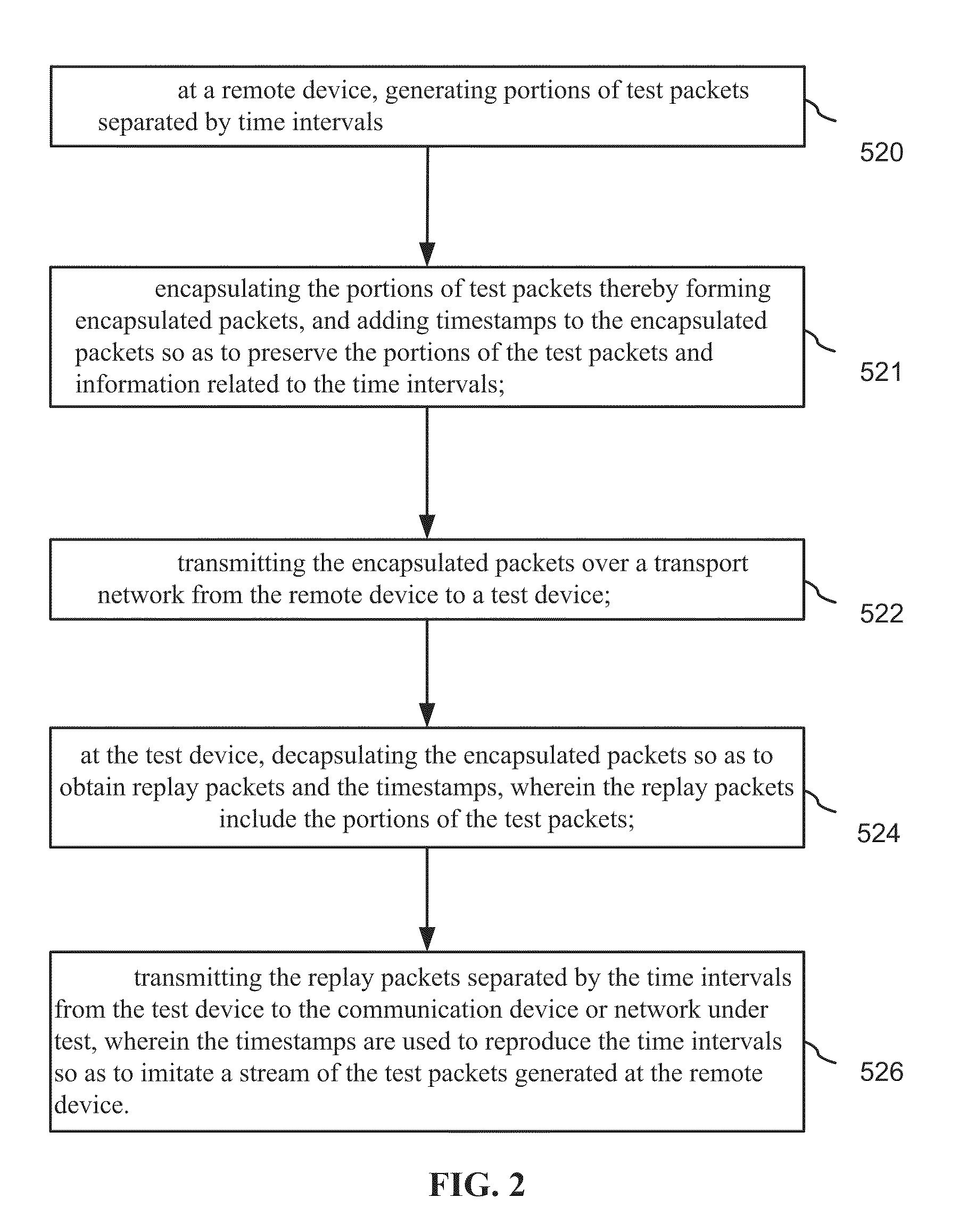
[0034]The remote test system 510 generates test packets which are sent over the transport network 112 e.g. to the local test device 512 and replayed therefrom to the device under test 514; the packet are encapsulated and their timing is preserved in the encapsulation. At the local test device 512 the packets are decapsulated; the order of the test packets and inter-packet time intervals are restored based on timestamps ...


PUM


Abstract

A test device includes a packet input receiver for receiving encapsulated packets from a network; a packet reader for extracting timing information from the encapsulated packets, and for decapsulating encapsulated packets so as to obtain test packets; a FIFO queue for storing the test packets; a packet controller for reading the test packets from the FIFO queue and writing the test packets into a de-jitter buffer in accordance with the timing information, the de-jitter buffer for storing the reordered test packets; and, a packet output generator for providing the test packets to a target device wherein time intervals between the test packets are reproduced using the timing information.

Description

CROSS-REFERENCE TO RELATED APPLICATIONS[0001]The present invention claims priority from U.S. Provisional Patent Application Nos. 61 / 355,040 and 61 / 355,075, both filed Jun. 15, 2010, incorporated herein by reference.TECHNICAL FIELD[0002]The present invention relates generally to networking and communications technology and, more particularly, to methods of testing a network and devices therein.BACKGROUND OF THE INVENTION[0003]Communication networks are widely used today; the variety of networks includes the Internet, wide-area networks (WANs), local-area networks (LANs), telephony networks, and wireless networks. The importance of network monitoring and testing is growing as well as the requirements for related methods and equipment. One particular aspect of network testing is active testing when a test device, e.g. a packet generator, injects test traffic into a device under test or into a portion of a network being tested.[0004]Conventional test devices support a plurality of proto...

Claims


Application Information

Patent Timeline
IPC IPC(8): H04L12/26
CPCH04L12/2697H04L43/026H04L43/062H04L43/12H04L43/50H04L43/106H04L43/022H04L43/028H04L43/18H04L43/0829H04L2212/00
Inventor HAVER, JOEHIDAI, TAKASHIBAUER, SAMHSUEH, CANNING
Owner VIAVI SOLUTIONS INC
Learn More