Wireless base station and wireless communication method

Inactive Publication Date: 2011-12-15
KYOCERA CORP
View PDF2 Cites 13 Cited by
  • Summary
  • Abstract
  • Description
  • Claims
  • Application Information

AI Technical Summary

Benefits of technology

[0027]According to the present invention, the wireless base station can select an antenna suitable for varying transmission environments and thus can perform a stable communication.
[0028]Moreover, according to the present invention, the wireless base station selects a transmission method suitable for t

Problems solved by technology

However, since the antenna elements are arranged at long intervals, this wireless base station has a problem that it is difficult to control directivity to separate transmission waves (desired waves) transmitted from a terminal A and transmission waves (interference waves) transmitted from a terminal B. In order to address such problem, there is suggested an antenna device of a wireless base station which has antenna elements (group B) arranged at wavelength intervals different from those of a group A and, if it is not possible to perform a desired directivity control, changes directivity characteristics by switching from any of antennas in the group A being used

Method used


Image

  • Wireless base station and wireless communication method
  • Wireless base station and wireless communication method
  • Wireless base station and wireless communication method

Examples


Example

First Embodiment

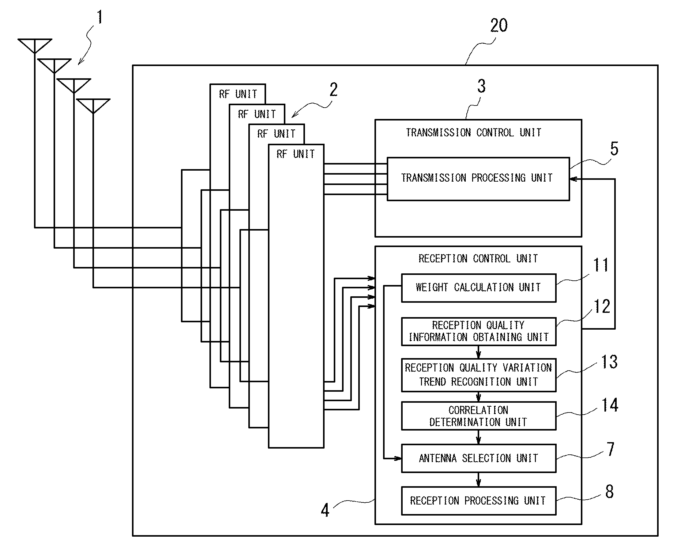
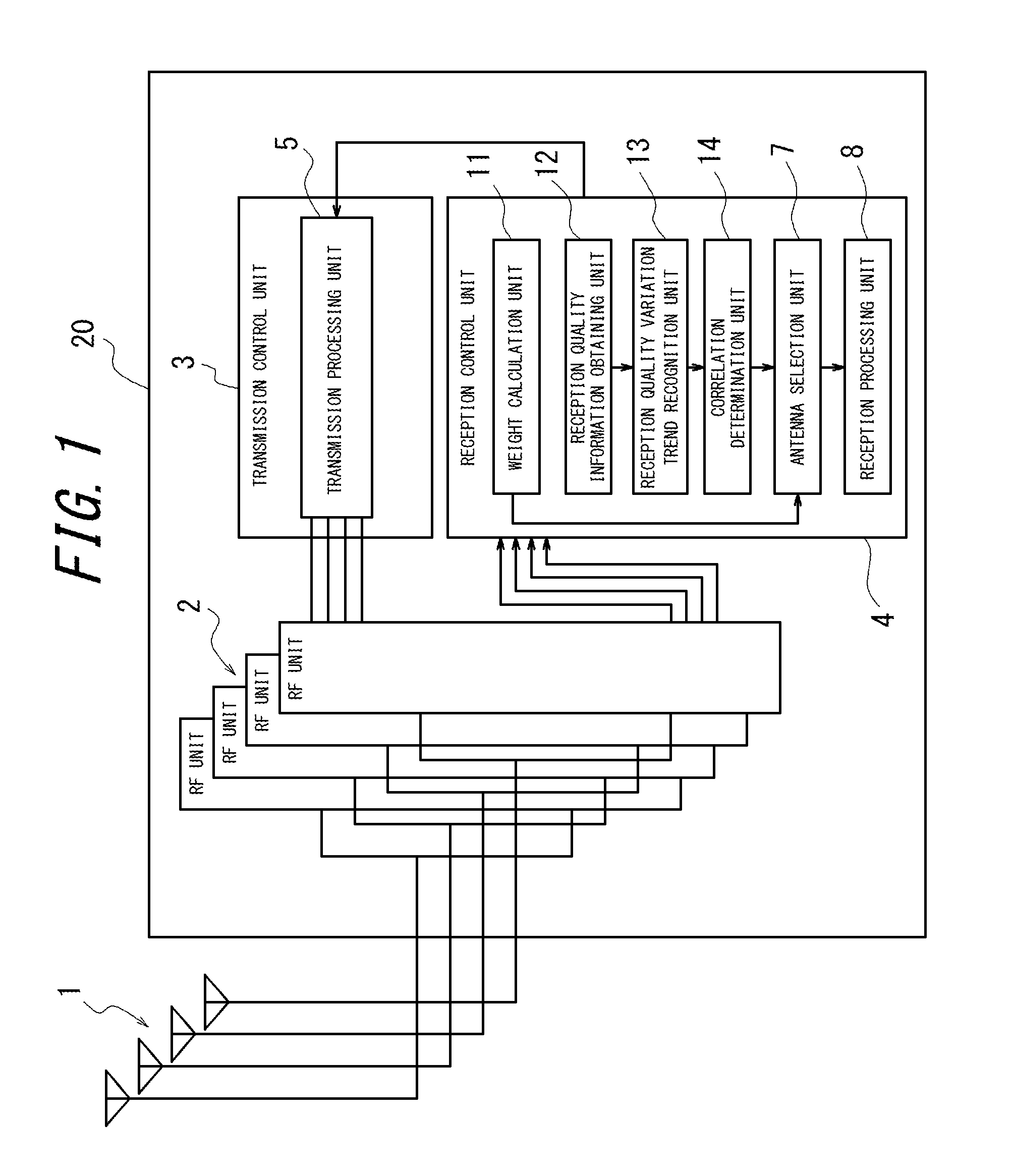
[0040]FIG. 1 is a block diagram illustrating an exemplary configuration of a wireless base station according to a first embodiment of the present invention. In FIG. 1, a wireless base station 20 includes a plurality of antenna elements 1, a plurality of wireless (RF) units 2 provided to respective antennas for up / down conversion of radio signals from a counterpart communication apparatus, a transmission control unit 3 and a reception control unit 4. The transmission control unit 3 has a transmission processing unit 5. The reception control unit 4 has a weight calculation unit (calculation unit) 11, a reception quality information obtaining unit (obtaining unit) 12, a reception quality variation trend recognition unit (recognition unit) 13, a correlation determination unit (determination unit) 14, an antenna selection unit (selection unit) 7 and a reception processing unit 8. The weight calculation unit 11 calculates a weight of each of the plurality of antennas. The ...

Example

Second Embodiment

[0068]FIG. 5 is a block diagram illustrating an exemplary configuration of a wireless base station according to a second embodiment of the present invention. As shown in FIG. 5, a wireless base station 40 includes a plurality of antenna elements 21, which is an array antenna, a plurality of wireless (RF) units 22 for up / down conversion of radio signals from a communication apparatus on a counterpart side (communication counterpart apparatus), a transmission control unit 23 and a reception control unit 24. The transmission control unit 23 has a transmission processing unit 25. The reception control unit 24 has a weight calculation unit (calculation unit) 31, a reception quality information obtaining unit (obtaining unit) 32, a reception quality variation trend recognition unit (recognition unit) 33, a correlation determination unit (determination unit) 34, an antenna selection unit (selection unit) 27 and a reception processing unit 28. The weight calculation unit 31...


PUM


Abstract

A reception quality information obtaining unit obtains reception quality information indicating reception quality of each of a plurality of antennas at predetermined intervals. A reception quality variation trend recognition unit recognizes a variation trend of a value in relation to reception quality of each of the antennas obtained. A correlation determination unit determines a degree of correlation between the antennas based on the variation trend of the value in relation to the reception quality of each of the antennas recognized. An antenna selection unit selects at least two antennas to be used for wireless communication, based on the degree of correlation between the antennas determined by the correlation determination unit .

Description

CROSS REFERENCE TO RELATED APPLICATIONS[0001]This application claims priority to and the benefit of Japanese Patent Application No. 2008-169350 (filed on Jun. 27, 2008) and Japanese Patent Application No. 2008-196827 (filed on Jul. 30, 2008), the entire contents of which are incorporated herein by reference.TECHNICAL FIELD[0002]The present invention relates to a wireless base station having an adaptive array antenna and a wireless communication method of the wireless base station.BACKGROUND ART[0003]At the wireless base station for performing communications by using an adaptive array antenna, the adaptive array antenna has different effects based on arrangements of antenna elements. When the antenna elements of the adaptive array antenna are arranged at short intervals, antenna correlation becomes high, which enables to handle fluctuations of fading. In contrast, when the antenna elements of the adaptive array antenna are arranged at long intervals, the antenna correlation becomes l...

Claims


Application Information

Patent Timeline
IPC IPC(8): H04B15/00H04B7/00
CPCH01Q3/24H04B7/0413H04W72/085H04B7/0874H04W72/046H04B7/0808H04W72/542H04B7/061H04B7/0691H04B7/0814
Inventor KITAHARA, MINAKO
Owner KYOCERA CORP
Why Eureka
Try Eureka