Method of manufacturing sprocket segment, and sprocket segment

a technology of sprocket and sprocket segments, which is applied in the direction of hoisting equipment, transportation and packaging, and other domestic objects, can solve the problems of difficult to form the tooth surface with a high degree of precision, the dies are prone to breakage, and the sprocket is large and has a plurality of teeth. , to achieve the effect of improving the forming precision of the tooth surface, suppressing the increase of forming pressure, and improving the forming precision

Inactive Publication Date: 2011-12-15
KOMATSU LTD
View PDF5 Cites 2 Cited by
  • Summary
  • Abstract
  • Description
  • Claims
  • Application Information

AI Technical Summary

Benefits of technology

[0034]Accordingly, the burr part where burrs will be formed in a part of the sprocket segment can be formed in a part outside the tooth surface. Since it is possible to avoid that the burr removal portion adversely affects the tooth surface of the sprocket segment, the forming precision of the tooth surface can be improved. Also, since the sprocket segment is for

Problems solved by technology

In the case of a large sprocket used for a lower traveling unit of a tracked vehicle such as construction machine (e.g., hydraulic excavator, and bulldozer) and agricultural vehicle, even recent years, it is difficult to integrally form such a large sprocket with a plurality of teeth.
However, both the aforementioned conventional vertically and horizontally stamping methods of manufacturing a sprocket segment have the following pro

Method used


Image

  • Method of manufacturing sprocket segment, and sprocket segment
  • Method of manufacturing sprocket segment, and sprocket segment
  • Method of manufacturing sprocket segment, and sprocket segment

Examples


Embodiment Construction

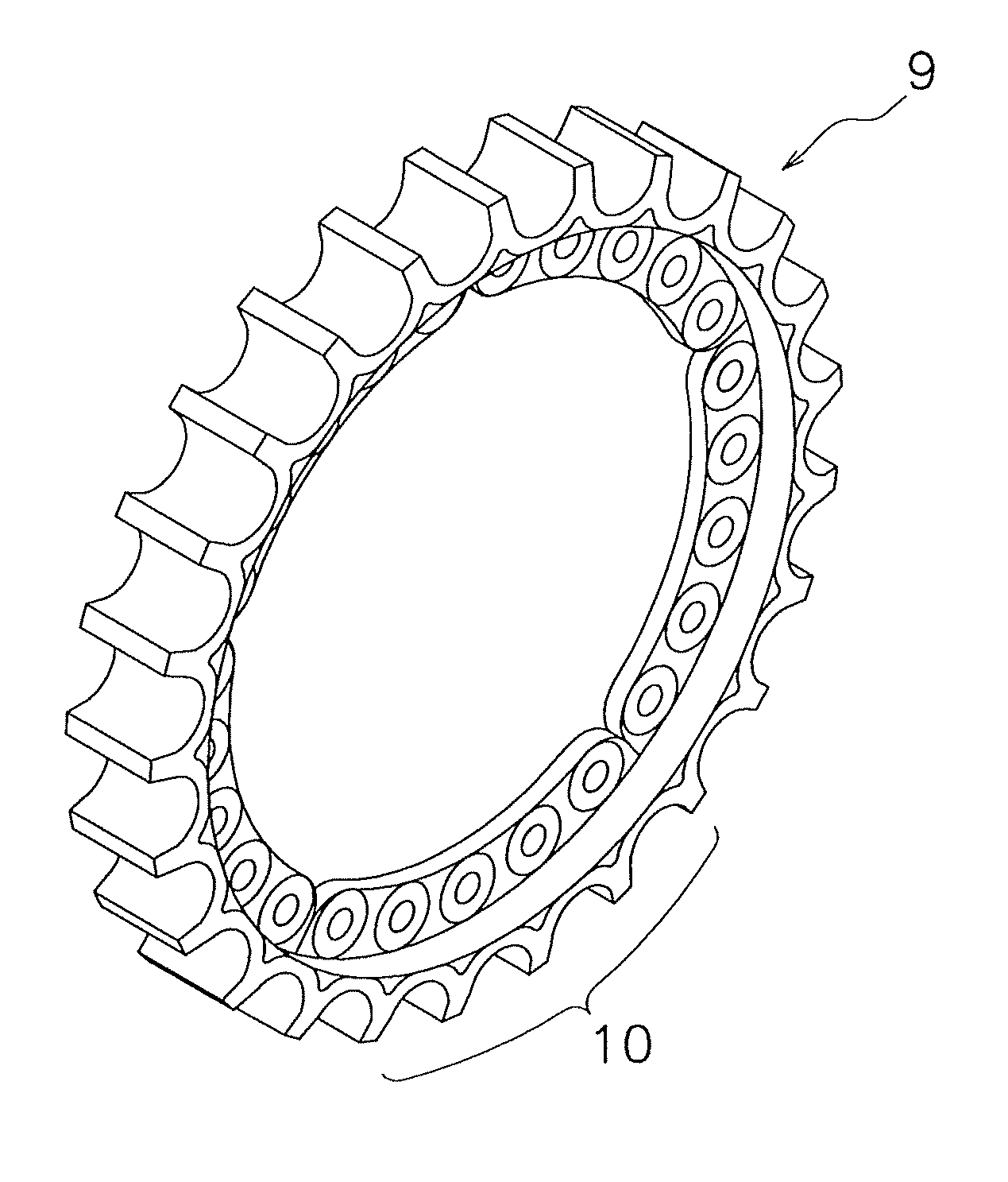
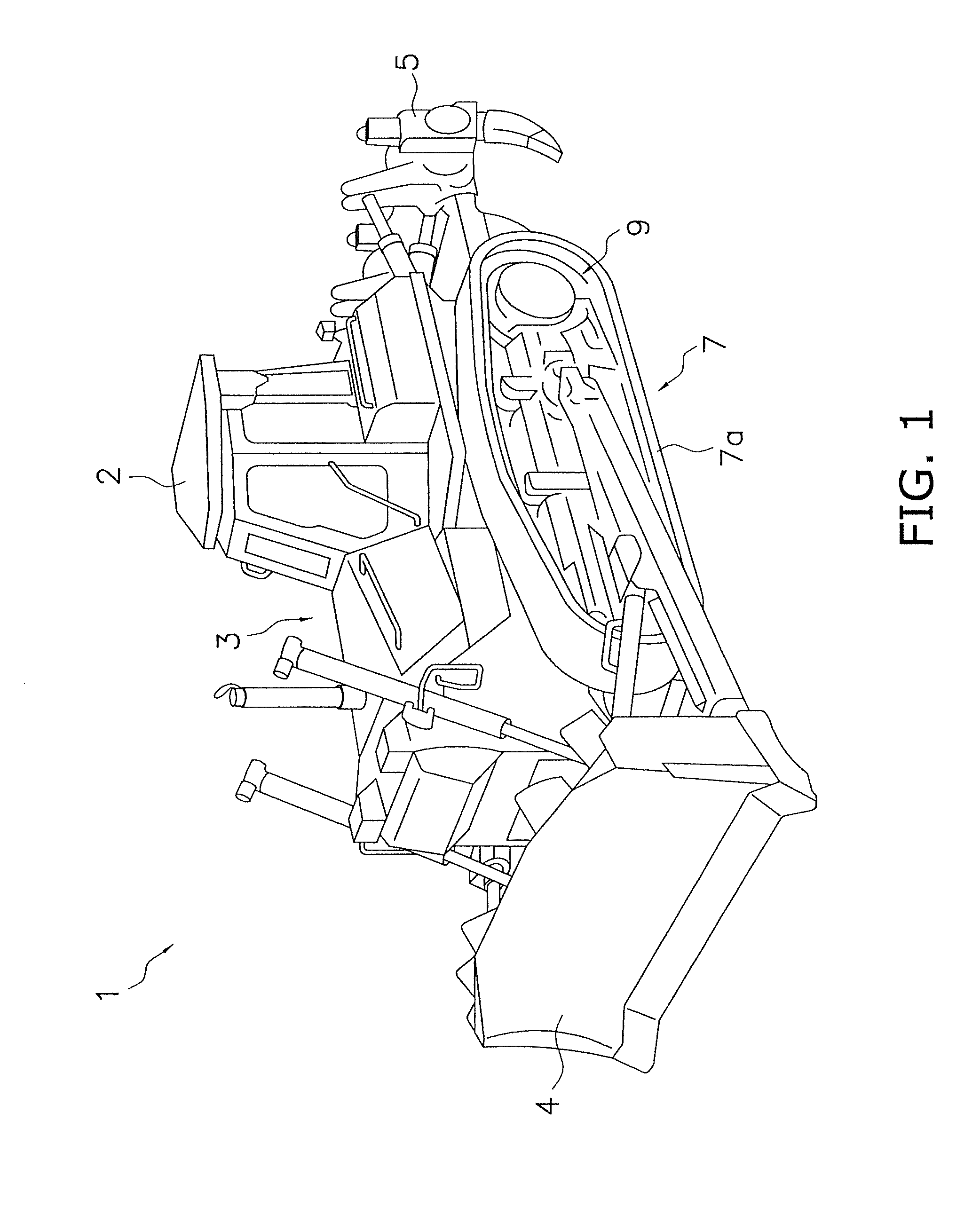
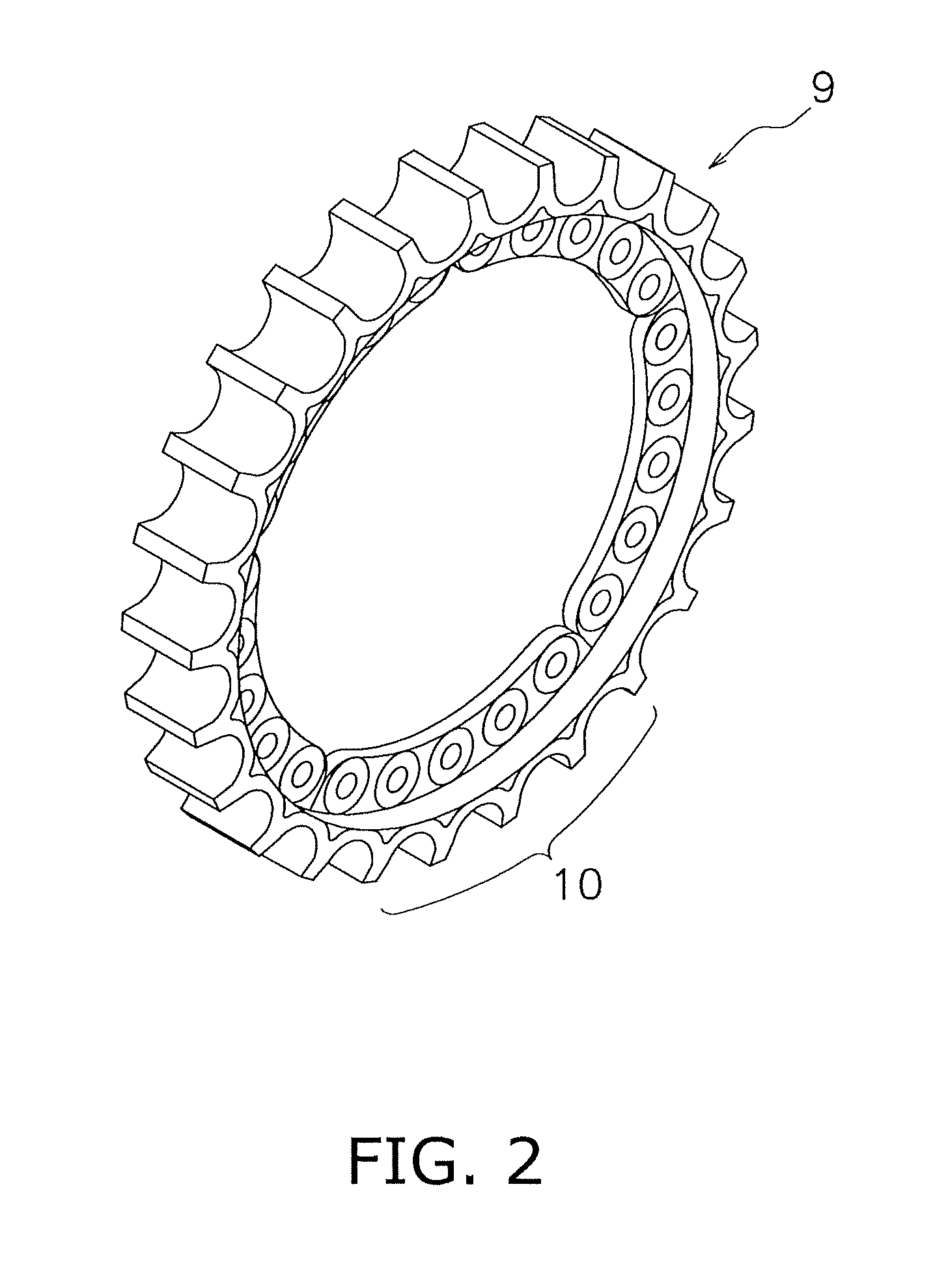
[0047]With reference to FIGS. 1 to 11, the following description will describe a method of manufacturing a sprocket segment 10, and a bulldozer 1, which includes the sprocket segments 10 manufactured by this method according to an embodiment of the present invention.

Construction of Bulldozer 1

[0048]The bulldozer 1 according to this embodiment is a construction machine that levels rough ground, and mainly includes a cab 2, a main unit frame 3, a blade 4, a ripper (working unit) 5, and a traveling unit 7 as shown in FIG. 1.

[0049]The cab 2 includes an operator seat (driver's seat) on which a driver (operator) sits, and levers, pedals, meters and the like for various types of operation.

[0050]Working equipment such as blade 4 and ripper 5, and the traveling unit 7 are mounted to the main unit frame 3. The cab 2 is installed on the upper part of the main unit frame 3.

[0051]The blade 4 is a working unit that is mounted to the front part of the main unit frame 3 to dig in the ground and to ...


PUM

PropertyMeasurementUnit
Heightaaaaaaaaaa

Abstract

A method of manufacturing a sprocket segment that is formed by forging as one of a plurality of circumferentially divided parts of a sprocket having a plurality of teeth arranged on an outer peripheral surface of a circular flange, the method includes: forming a material of the sprocket segment into an initial formed state in an initial forming step; and subjecting the sprocket segment in dies to a finish forming process with a tooth trace direction of the sprocket segment as viewed in cross-section of the sprocket segment being inclined relative to a forging direction of the dies in a finish forming step.

Description

CROSS-REFERENCE TO RELATED APPLICATIONS[0001]This national phase application claims priority to Japanese Patent Application No. 2009-036961 filed on Feb. 19, 2009. The entire disclosure of Japanese Patent Application No. 2009-036961 is hereby incorporated herein by reference.TECHNICAL FIELD[0002]The present invention relates to method of manufacturing a sprocket segment, die equipment for manufacturing a sprocket segment, and a sprocket segment to compose a sprocket of tracked vehicle including a construction machine such as bulldozer and agricultural vehicle.BACKGROUND INFORMATION[0003]A sprocket has a plurality of teeth are arranged on the outer peripheral part of the sprocket. In the case of a large sprocket used for a lower traveling unit of a tracked vehicle such as construction machine (e.g., hydraulic excavator, and bulldozer) and agricultural vehicle, even recent years, it is difficult to integrally form such a large sprocket with a plurality of teeth. For this reason, a plu...

Claims


Application Information

Patent Timeline
IPC IPC(8): E02F9/02B21K1/30
CPCB21J5/00B21J5/02B21K1/30B21K23/02Y10T29/49474E02F9/20F16H55/12F16H55/30Y10T29/49467E02F9/02
Inventor KAWAHARA, FUMIAKIWANG, TAOKUSADA, SHOHEI
Owner KOMATSU LTD
Why Eureka
Try Eureka