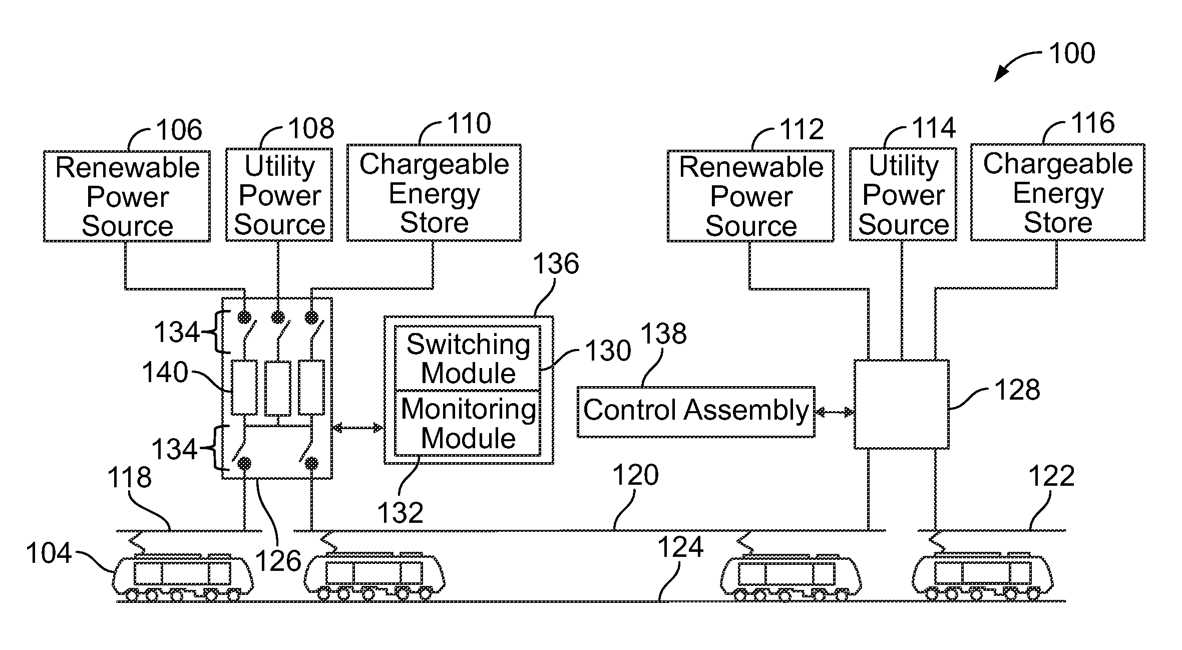
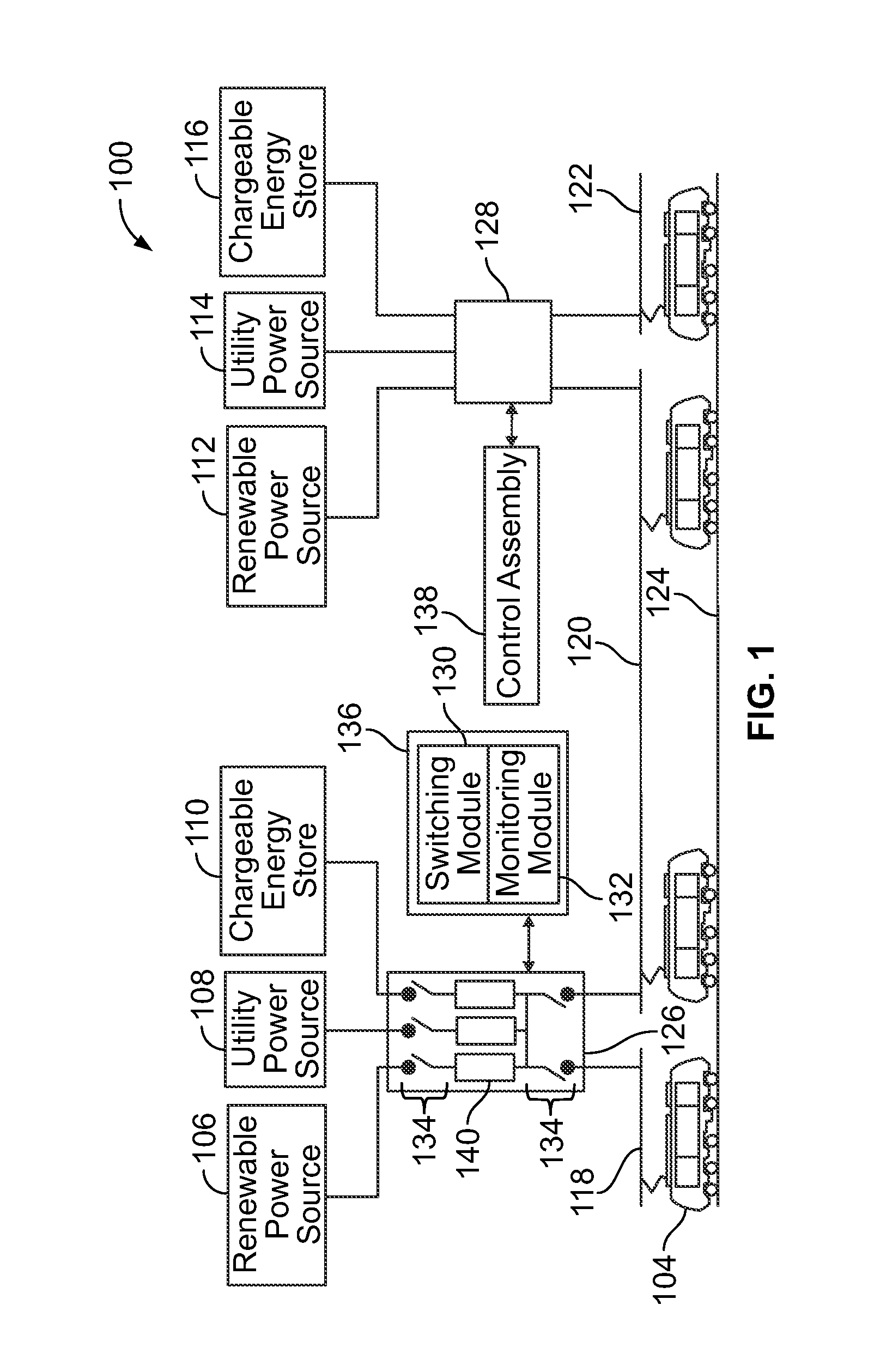
Control assembly and control method for supplying power to electrified rail vehicles

a technology of control assembly and electrified rail, which is applied in the direction of process and machine control, material dimension control, instruments, etc., can solve the problems of inability to introduce additional current sources for rail vehicles, inability to adapt the available supply of electric current, and greater supply of curren

Active Publication Date: 2011-12-15
GE GLOBAL SOURCING LLC
View PDF8 Cites 54 Cited by
  • Summary
  • Abstract
  • Description
  • Claims
  • Application Information

AI Technical Summary

Problems solved by technology

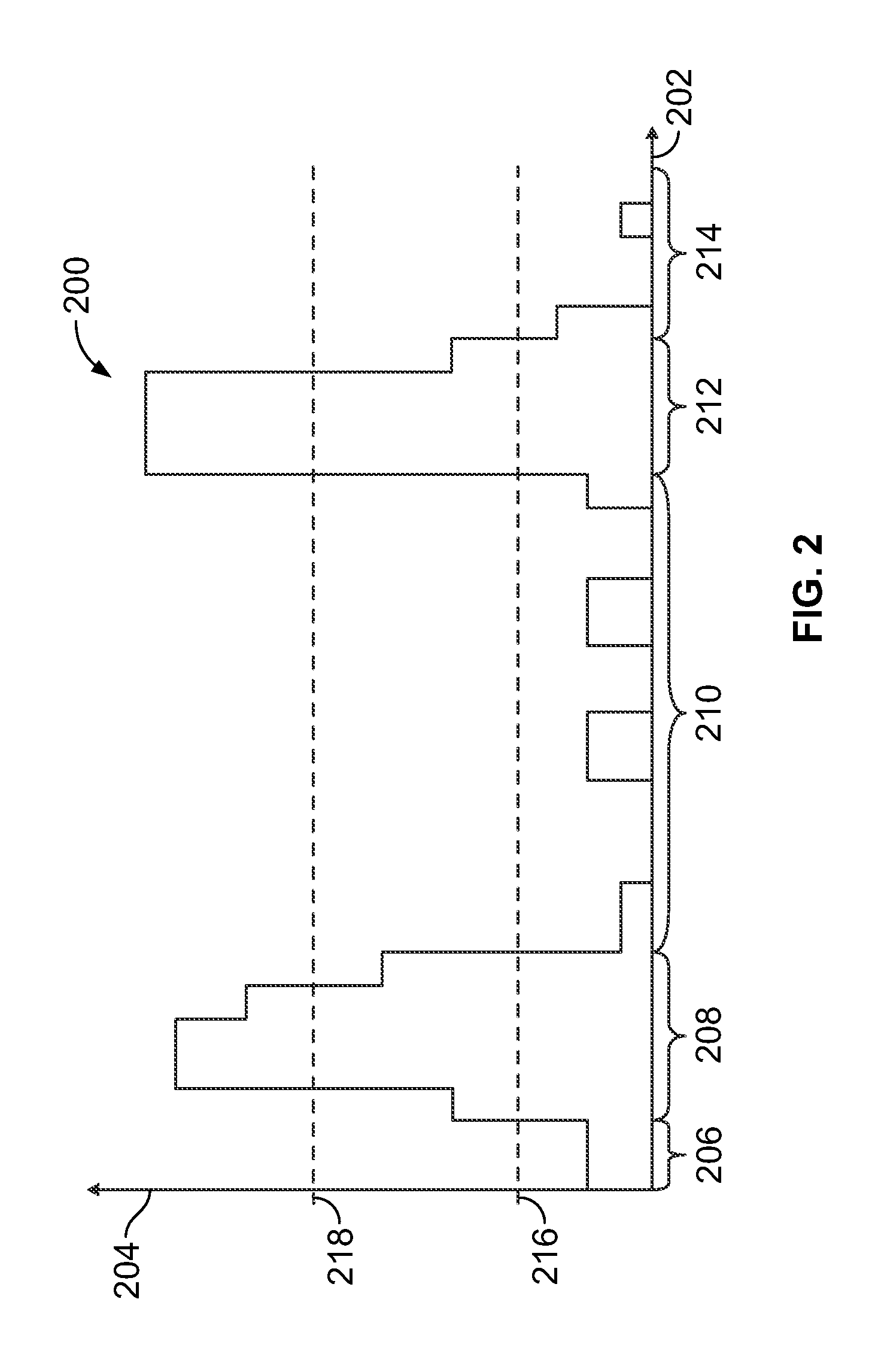
One problem with some known electrified rail systems is that the available supply of electric current may not adapt as the demand for the current changes.
As a result, the supply of current may be greater than the need of the rail vehicles or the supply may be unable to meet the need for electric current to power the rail vehicles.
Another problem with some known electrified rail systems is the inability to introduce additional sources of current for the rail vehicles.
For example, some systems may be limited to supplying current from existing utilities rather than allowing other sources of current to supply current to the rail vehicles.
The utilities that receive the regenerative current may have limits on the regenerative current that can be received from the rail vehicles.
For example, during periods of relatively low traffic density of rail vehicles, the utility that supplies power to the rail vehicles may be unable to accept most or all of the regenerative current.
As a result, the electronic hardware used to transmit, receive, and interpret the control signals adds to the cost of providing and / or maintaining the rail vehicles.

Method used


Image

  • Control assembly and control method for supplying power to electrified rail vehicles
  • Control assembly and control method for supplying power to electrified rail vehicles
  • Control assembly and control method for supplying power to electrified rail vehicles

Examples


Embodiment Construction

[0019]The foregoing brief description, as well as the following detailed description of certain embodiments of the present subject matter, will be better understood when read in conjunction with the appended drawings. To the extent that the figures illustrate diagrams of the functional blocks of various embodiments, the functional blocks are not necessarily indicative of the division between hardware circuitry. Thus, for example, one or more of the functional blocks (for example, processors or memories) may be implemented in a single piece of hardware (for example, a general purpose signal processor, microcontroller, random access memory, hard disk, and the like). Similarly, the programs may be stand alone programs, may be incorporated as subroutines in an operating system, may be functions in an installed software package, and the like. The various embodiments are not limited to the arrangements and instrumentality shown in the drawings.

[0020]As used herein, an element or step reci...


PUM


Abstract

A control assembly includes a monitoring module and a switching module. The monitoring module determines a load demand of a first rail vehicle traveling along a track, wherein the first rail vehicle is supplied with electric current from a plurality of power sources over a conductive pathway extending along the track. The switching module is communicatively coupled with the monitoring module and is joined with a switch controller disposed between the power sources and the conductive pathway. The switching module directs the switch controller to change which of the power sources supply the electric current to the first rail vehicle over the conductive pathway based on the load demand.

Description

BACKGROUND OF THE INVENTION[0001]The subject matter described herein relates generally to electrified rail systems.[0002]Known electrified rail systems include rail vehicles that are powered by electric current. The rail vehicles may receive current from a utility, such as an electric utility or company that generates, transmits, and / or distributes electric current to a general population. The current is supplied along feeder lines or cables that deliver the current to substations located along a track on which the rail vehicles travel. The substations supply the current to overhead catenaries that transmit the current to the rail vehicles.[0003]One problem with some known electrified rail systems is that the available supply of electric current may not adapt as the demand for the current changes. For example, the supply of current may not change in response to changes in the rail traffic throughout a day. As a result, the supply of current may be greater than the need of the rail v...

Claims


Application Information

Patent Timeline
Patent Type & Authority Applications(United States)
IPC IPC(8): G06F1/28
CPCB60M3/00
Inventor KUMAR, AJITH KUTTANNAIRWORDEN, BRET
Owner GE GLOBAL SOURCING LLC
Why Eureka
Try Eureka