Finger bar

a finger bar and finger technology, applied in the field of finger bars, can solve the problems of complex design of the coupling device, and achieve the effects of easy replacement of single partial rails, simplified handling of parts, and greater cutting width

Inactive Publication Date: 2011-12-22
CLAAS SELBSTFAHRENDE ERNTEMASCHINEN GMBH
View PDF2 Cites 13 Cited by
  • Summary
  • Abstract
  • Description
  • Claims
  • Application Information

AI Technical Summary

Benefits of technology

[0007]Displacement in the finger bar, which would interfere with the unimpeded movement of the oscillating cutting system, is thereby prevented. Moreover, form-locking connections make it possible to easily connect two or more partial rails to form a knife bar in order to fulfill the increasing requirements for greater cutting width. The form-locking connection also makes it possible to easily replace a single partial rail if this should become necessary. Due to the form-locking connection and the related simplicity of assembly, the knife bar can be advantageously composed of a plurality of partial rails, each of which is less than approximately three meters in length. Connecting partial rails having said length is advantageous in terms of processes within an organization, since the handling thereof is simplified. The same applies for the shipment of partial rails as replacement parts, since it is easier to ship partial rails having a limited length.
[0008]Preferably, the partial rails can comprise, on the end faces thereof, a projection or a recess which corresponds to the contour of the projection, wherein the projection and the recess have supplementary undercuts which form abutments. The abutments formed by the supplementary undercuts help to retain the form-locking connection, thereby preventing separation via bending—in particular in the region of the recess enclosing the projection—which would be caused by the tensile forces to be transferred when vertical deflection occurs.

Problems solved by technology

Such a coupling device has a very complex design, however.

Method used


Image

  • Finger bar
  • Finger bar
  • Finger bar

Examples


Embodiment Construction

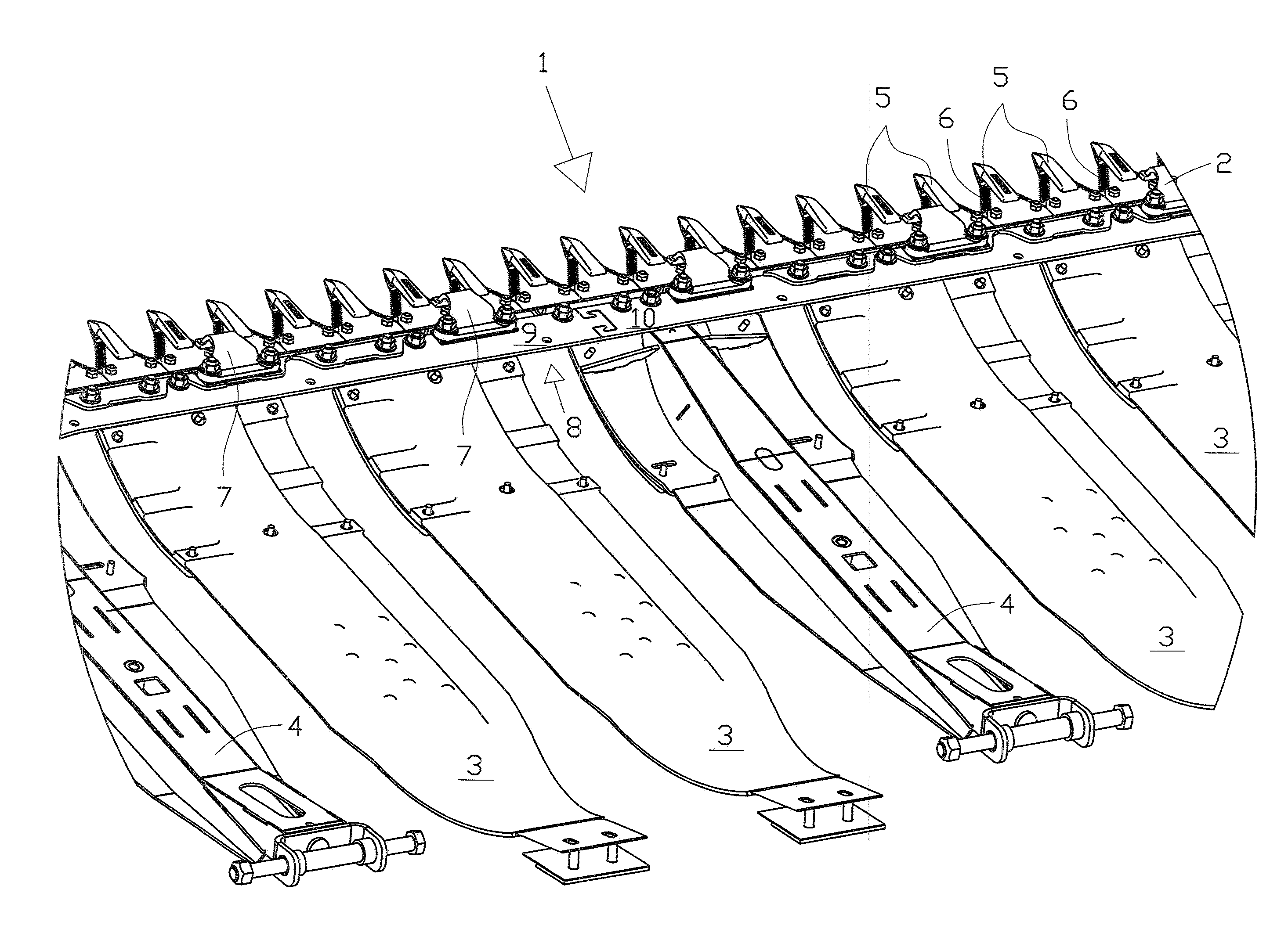
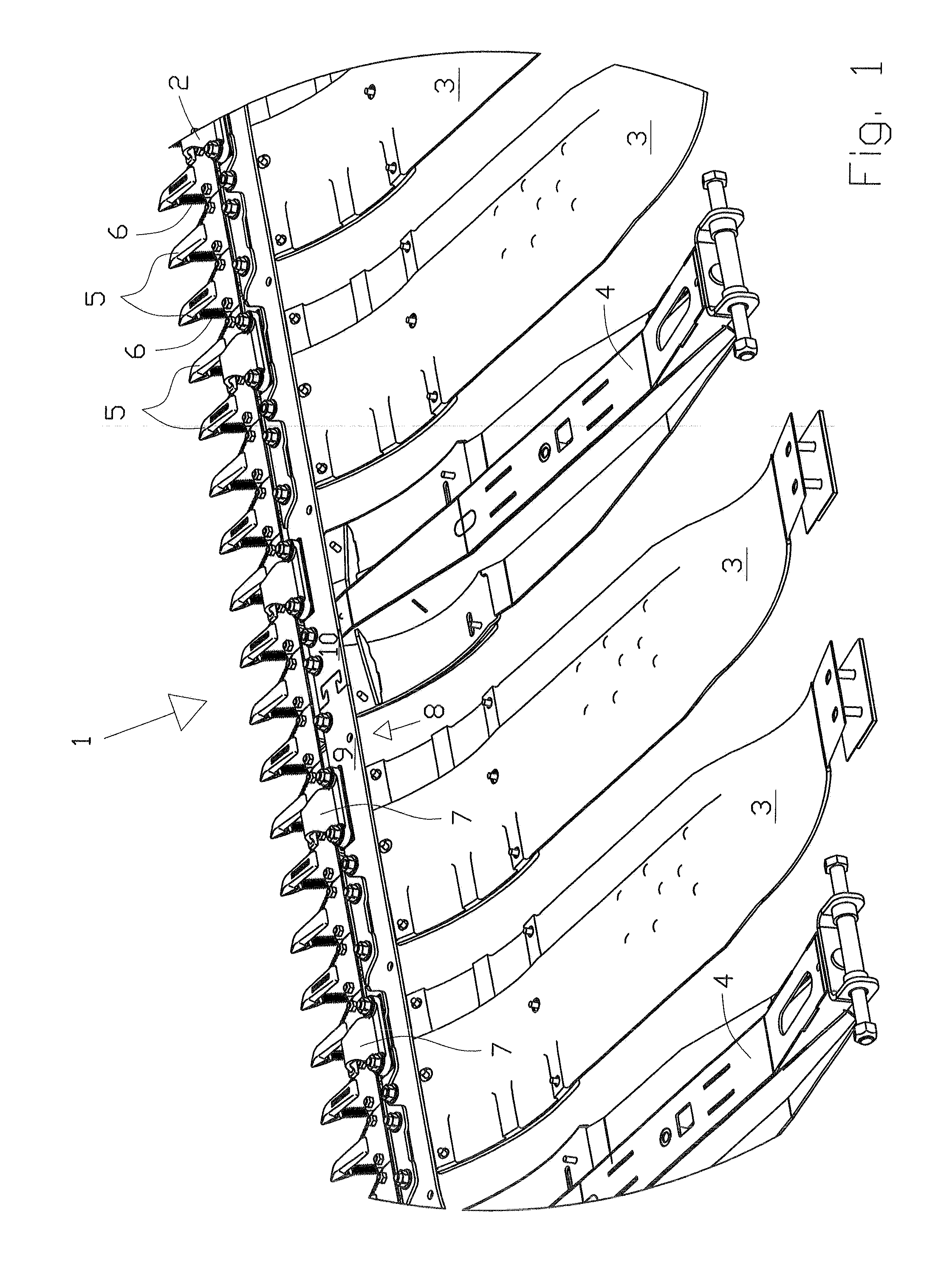
[0017]To cut the crop, a header which is known per se and is shown in a detailed view in FIG. 1 is disposed on the front side of a combine harvester which is not shown in the drawing. The header mainly comprises a device for conveying cut crop, a flexible cutter bar 1 on which a cutting system 2 is disposed, and a large number of adjacently disposed undercarriage skids 3. Undercarriage skids 3 are composed of an inherently resilient plastic having a smooth surface and good gliding properties. In addition, profiled base carriers 4 which extend approximately horizontally and are interspaced are provided on the header. The front ends of undercarriage skids 3 are connected to cutter bar 1 via threaded connections. Cutting system 2 disposed on cutter bar 1 comprises knives 6 which are disposed on a reciprocating rail, and knife guards 5 in the form of counter-blades.

[0018]Cutting system 2 is connected to the header via a knife bar 8. The header is suitable for harvesting grain, beans, or...


PUM


Abstract

A finger bar for a header has a knife bar with at least two partial rails which are interconnectable at the end faces thereof, and a cutting system which can move back and forth in an oscillating manner, is attachable to the knife bar, and is deflectable transversely to the longitudinal axis thereof, in the vertical direction, and the partial rails are interconnectable in a form-locking manner on the end faces thereof that face each other.

Description

CROSS-REFERENCE TO RELATED APPLICATION[0001]The invention described and claimed hereinbelow is also described in German Patent Application DE 10 2010 017 502.1 filed on Jun. 22, 2010. This German Patent Application, whose subject matter is incorporated here by reference, provides the basis for a claim of priority of invention under 35 U.S.C. 119(a)-(d).BACKGROUND OF THE INVENTION[0002]The present invention relates to a finger bar.[0003]Finger bars for a header comprise a knife bar onto which a cutting system can be attached, said cutting system being movable back and forth in an oscillating manner transversely to the direction of travel of a self-propelled harvesting machine. The cutting system comprises a rail to which knives are attached and is movable in a reciprocating manner by a drive, and comprises a knife bar to which knife guards are attached; said knife guards guide the knives and function as counter-blades. To compensate for ground contours, the cutting system can be defl...

Claims


Application Information

Patent Timeline
Patent Type & Authority Applications(United States)
IPC IPC(8): A01D34/14
CPCA01D41/14A01D34/14
Inventor BUERMANN, DOMINIKLIEDMEIER, STEFAN
Owner CLAAS SELBSTFAHRENDE ERNTEMASCHINEN GMBH
Why Eureka
Try Eureka