Exhaust manifold with baffle plate

a technology of exhaust manifold and baffle plate, which is applied in the direction of machine/engine, engine components, silting apparatus, etc., can solve the problem that the mass of the motor flange cannot be easily reduced

Inactive Publication Date: 2011-12-22
BENTELER AUTOMOBILTECHNIK GMBH
View PDF9 Cites 11 Cited by
  • Summary
  • Abstract
  • Description
  • Claims
  • Application Information

AI Technical Summary

Benefits of technology

[0022]According to another advantageous feature of the present invention, the baffle plate can be securely fixed to the upper and lower housing shells in at least one area of the contact zone. Currently preferred is a fixed securement of the baffle plate to the upper and lower housing shells by a material joint, for example thermal joining, to effect a long service life. Thermal joining has the benefit that the exhaust manifold can be manufactured in a co

Problems solved by technology

The mass of the motor flange cannot easily be reduced because of its supp

Method used


Image

  • Exhaust manifold with baffle plate
  • Exhaust manifold with baffle plate
  • Exhaust manifold with baffle plate

Examples


Embodiment Construction

[0027]Throughout all the figures, same or corresponding elements may generally be indicated by same reference numerals. These depicted embodiments are to be understood as illustrative of the invention and not as limiting in any way. It should also be understood that the figures are not necessarily to scale and that the embodiments are sometimes illustrated by graphic symbols, phantom lines, diagrammatic representations and fragmentary views. In certain instances, details which are not necessary for an understanding of the present invention or which render other details difficult to perceive may have been omitted.

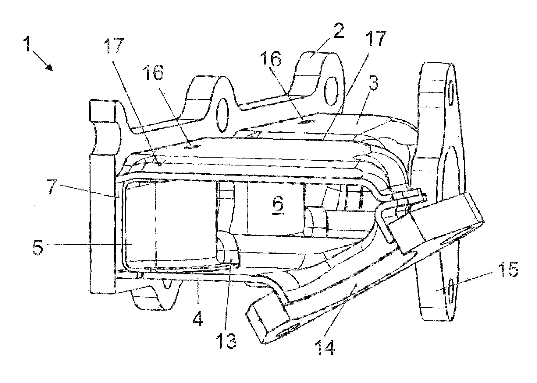
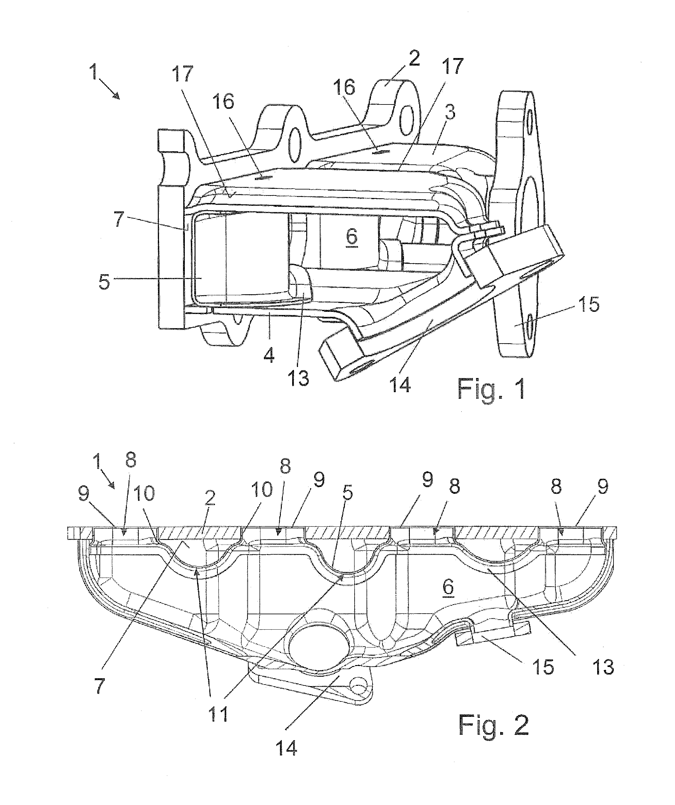
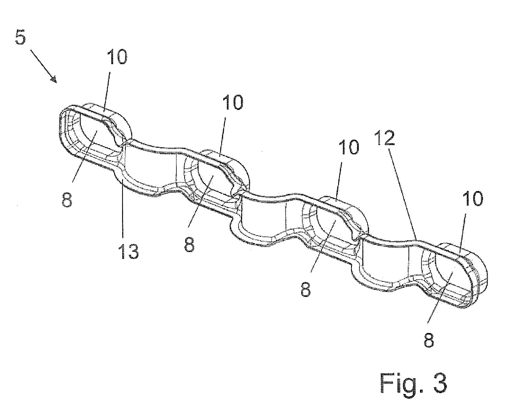
[0028]Turning now to the drawing, and in particular to FIG. 1, there is shown a perspective sectional view of an exhaust manifold according to the present invention, generally designated by reference numeral 1. The exhaust manifold 1 includes a motor flange 2 for attachment of the exhaust manifold 1 to a cylinder head of an internal combustion engine having at least two in-l...


PUM


Abstract

An exhaust manifold includes a housing formed of a thin-walled sheet metal part which is shaped in the form of a shell construction and has an upper housing shell and a lower housing shell to define an interior space. Received in the housing in an area proximate to a cylinder head of an internal combustion engine is a baffle plate which separates the interior space of the housing from a motor flange to secure the exhaust manifold to the cylinder head.

Description

CROSS-REFERENCES TO RELATED APPLICATIONS[0001]This application claims the priority of German Patent Application, Ser. No. 10 2009 058 047.6-13, filed Dec. 14, 2009, pursuant to 35 U.S.C. 119(a)-(d), the content of which is incorporated herein by reference in its entirety as if fully set forth herein.BACKGROUND OF THE INVENTION[0002]The present invention relates to an exhaust manifold, and more particularly to an exhaust manifold for attachment by a motor flange to a cylinder head of an internal combustion engine with at least two in-line cylinders.[0003]The following discussion of related art is provided to assist the reader in understanding the advantages of the invention, and is not to be construed as an admission that this related art is prior art to this invention.[0004]Exhausts from cylinders of a multi-cylinder internal combustion engines and carried away by an exhaust manifold are united in exhaust collectors. Exhaust manifolds can be made of cast steel or assembled from sing...

Claims


Application Information

Patent Timeline
IPC IPC(8): F01N13/10
CPCF01N13/10F01N13/1872F01N13/102
Inventor GRUSSMANN, ELMARFRICKE, FABIANNAUBERT, RALPH
Owner BENTELER AUTOMOBILTECHNIK GMBH
Why Eureka
Try Eureka