Modular direct current power source

Active Publication Date: 2011-12-22
ILLINOIS TOOL WORKS INC
View PDF5 Cites 67 Cited by
  • Summary
  • Abstract
  • Description
  • Claims
  • Application Information

AI Technical Summary

Problems solved by technology

Unfortunately, lengthy cables introduce significant inductance between a welding power source and a welding application.
Such co

Method used


Image

  • Modular direct current power source
  • Modular direct current power source
  • Modular direct current power source

Examples


Embodiment Construction

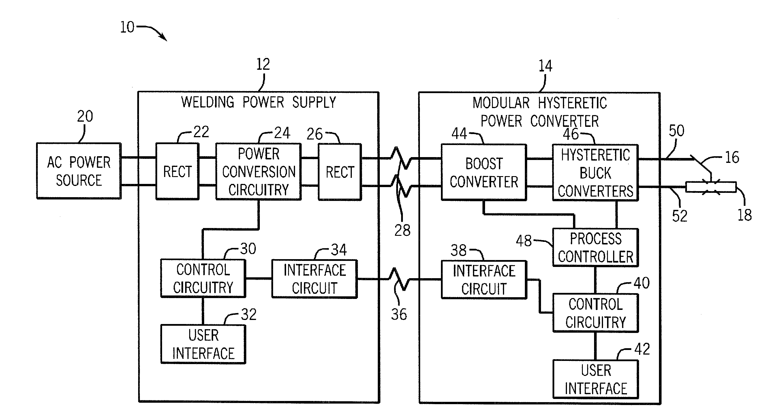
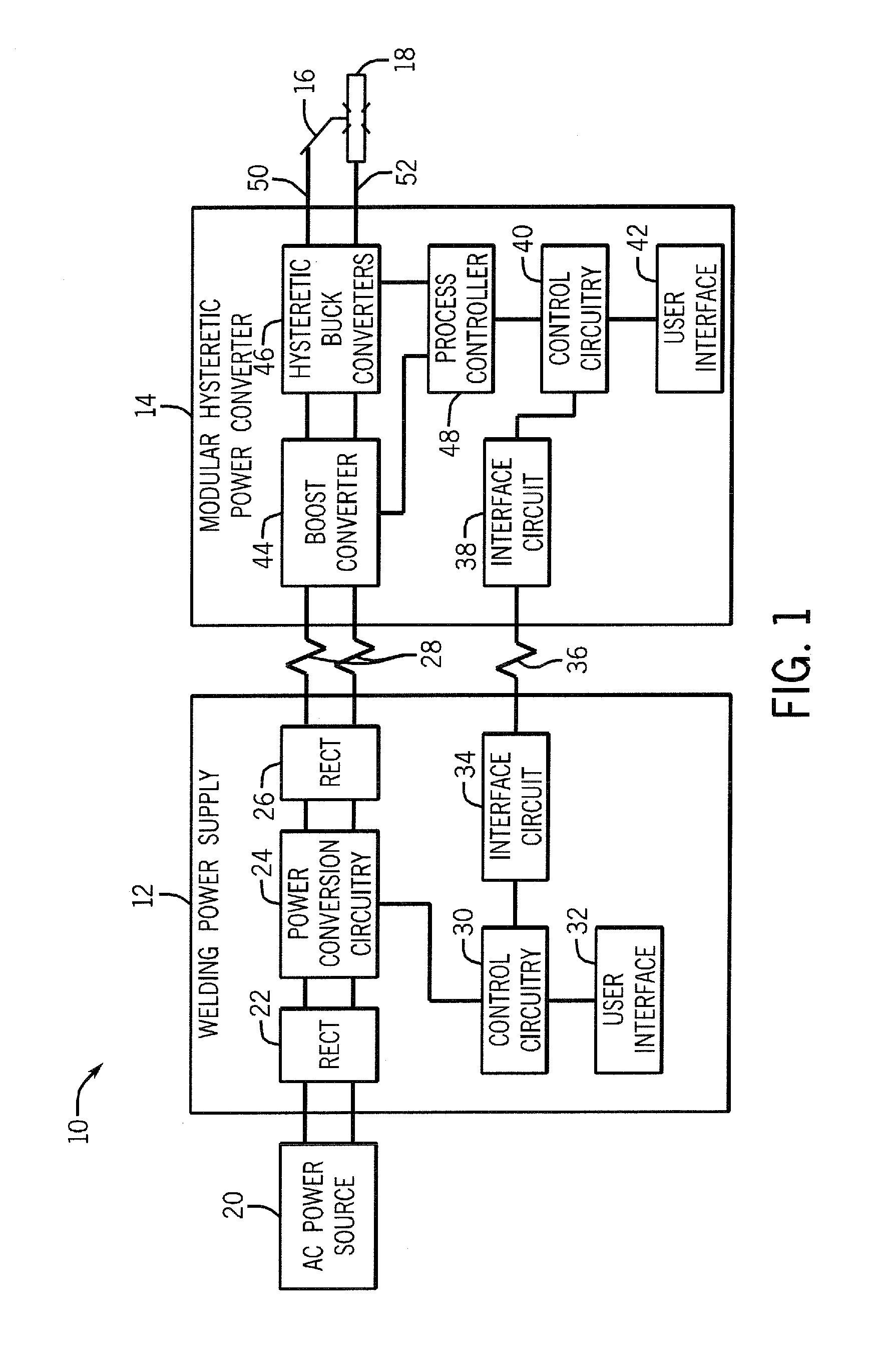
[0019]FIG. 1 is a schematic diagram of an embodiment of a welding system 10 which powers, controls, and provides supplies to a welding operation. As illustrated, the welding system 10 includes a welding power supply 12, a modular hysteretic power converter 14, a torch 16, and a workpiece 18. The welding power supply 12 receives primary power from an alternating current power source 20 (e.g., the AC power grid, an engine / generator set, or a combination thereof), conditions the input power, and provides an output power to one or more welding devices in accordance with demands of the system 10. The welding power source 12 includes a first rectifier 22, power conversion circuitry 24, and a second rectifier 26. The first rectifier 22 converts the alternating current (AC) from the power source 20 to a direct current (DC) and provides the DC to the power conversion circuitry 24. The power conversion circuitry 24 converts the DC power to voltages that may be used by other components of the ...


PUM


Abstract

A modular direct current power source is provided. One welding power supply system includes a plurality of hysteretic buck converters coupled in parallel. The hysteretic buck converters are configured to receive a common input and to provide combined output power to a common load based upon the common input.

Description

CROSS REFERENCE TO RELATED APPLICATIONS[0001]This application is a Non-Provisional patent application of U.S. Provisional Patent Application No. 61 / 355,983 entitled “Multi-phase Power Modulator Utilizing Hysteretic Control for a Welder Induction Heater, or Plasma Cutter”, filed Jun. 17, 2010, which is herein incorporated by reference.BACKGROUND[0002]The invention relates generally to welding systems and, more particularly, to a modular power source that may be used for welding applications.[0003]Welding is a process that has become increasingly ubiquitous in various industries and applications. Such processes may be automated in certain contexts, although a large number of applications continue to exist for manual welding operations. In both cases, such welding operations rely on a variety of types of equipment to ensure that the supply of welding consumables (e.g., wire feed, shielding gas, etc.) and welding power are provided to the weld in an appropriate amount at the desired tim...

Claims


Application Information

Patent Timeline
IPC IPC(8): B23K11/24
CPCB23K9/1043B23K9/09B23K9/091B23K9/1012B23K9/1075B23K9/133
Inventor SALSICH, ANTHONY VAN BERGEN
Owner ILLINOIS TOOL WORKS INC
Why Eureka
Try Eureka