Sensing display device

a display device and sensing technology, applied in the field of sensing display devices, can solve the problems of display moiré issue, high price, high resistance and high price of transparent conductive materials, etc., and achieve the effect of good sensitivity and good visual quality

Active Publication Date: 2011-12-22
AU OPTRONICS CORP
View PDF8 Cites 147 Cited by
  • Summary
  • Abstract
  • Description
  • Claims
  • Application Information

AI Technical Summary

Benefits of technology

[0009]The invention is directed to a sensing display device, which maintains a good sensitivity and has a good visual quality.
[0011]According to the above descriptions, the sensing element of the sensing display device of the invention includes mesh-pattern electrodes formed by intersected traces, wherein an acute angle is formed between the traces and a direction along which the pixel units are arranged. In this way, a visual Moiré issue caused by the mesh-pattern electrodes formed by the intersected traces and the pixel units arranged in an array can be avoided, so that a visual quality and a display quality of the sensing display device are improved.

Problems solved by technology

However, since the transparent conductive material has drawbacks of high resistance and high price, metal mesh is suggested to be used for fabricating the electrodes.
However, since the mesh-pattern of the electrodes and a pixel array in the display panel are both arranged periodically, the mesh-pattern electrodes and the pixel array may cause the display a visual Moiré issue.
Therefore, the sensing display device may have problems of image blur and poor visual quality.

Method used


Image

  • Sensing display device
  • Sensing display device
  • Sensing display device

Examples


second embodiment

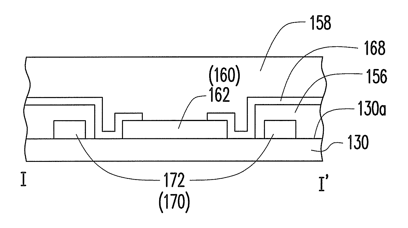
[0048]FIG. 3A is a top view of a sensing element of a sensing display device according to a second embodiment of the invention, FIG. 3B is a partial schematic diagram illustrating a configuration showing the relationship of a first electrode and a second electrode of FIG. 3A and pixel units, and FIG. 3C is a partial cross-sectional view of FIG. 3A along an I-I′ line and a pin junction area. Referring to FIG. 1B and FIG. 3A, the sensing element 150 is located on the array of the pixel units 124, and the sensing element 150 includes a plurality of sensor units 165. The sensor unit 165 is a mesh-pattern electrode. In the present embodiment, the sensor unit 165 includes a first electrode 162 and a second electrode 172. In detail, in the present embodiment, the sensing element 150 includes a plurality of the sensor units 165, which are arranged in a plurality of first serials 160 and a plurality of second serials 170. In the present embodiment, the first serial 160 is, for example, exten...

third embodiment

[0053]FIG. 5A is a top view of a sensing element of a sensing display device according to a third embodiment of the invention, FIG. 5B is a partial enlarged diagram of FIG. 5A and a partial schematic diagram illustrating a configuration showing the relationship of dummy electrodes and a pixel unit array. A structure of the sensing element of the present embodiment is similar to that of the sensing element of FIG. 3A, and a main difference there between is that in the present embodiment, a plurality of dummy electrodes 180 is disposed between the first electrodes 162 and the second electrodes 172. The dummy electrodes 180 are described below.

[0054]Referring to FIG. 5A and FIG. 5B, in the present embodiment, the dummy electrodes 180 are disposed between the first electrodes 162 and the second electrodes 172, and the dummy electrodes 180 are floated. The dummy electrode 180 is, for example, a mesh-pattern electrode formed by a plurality of fifth traces 182 and a plurality of sixth trac...

fourth embodiment

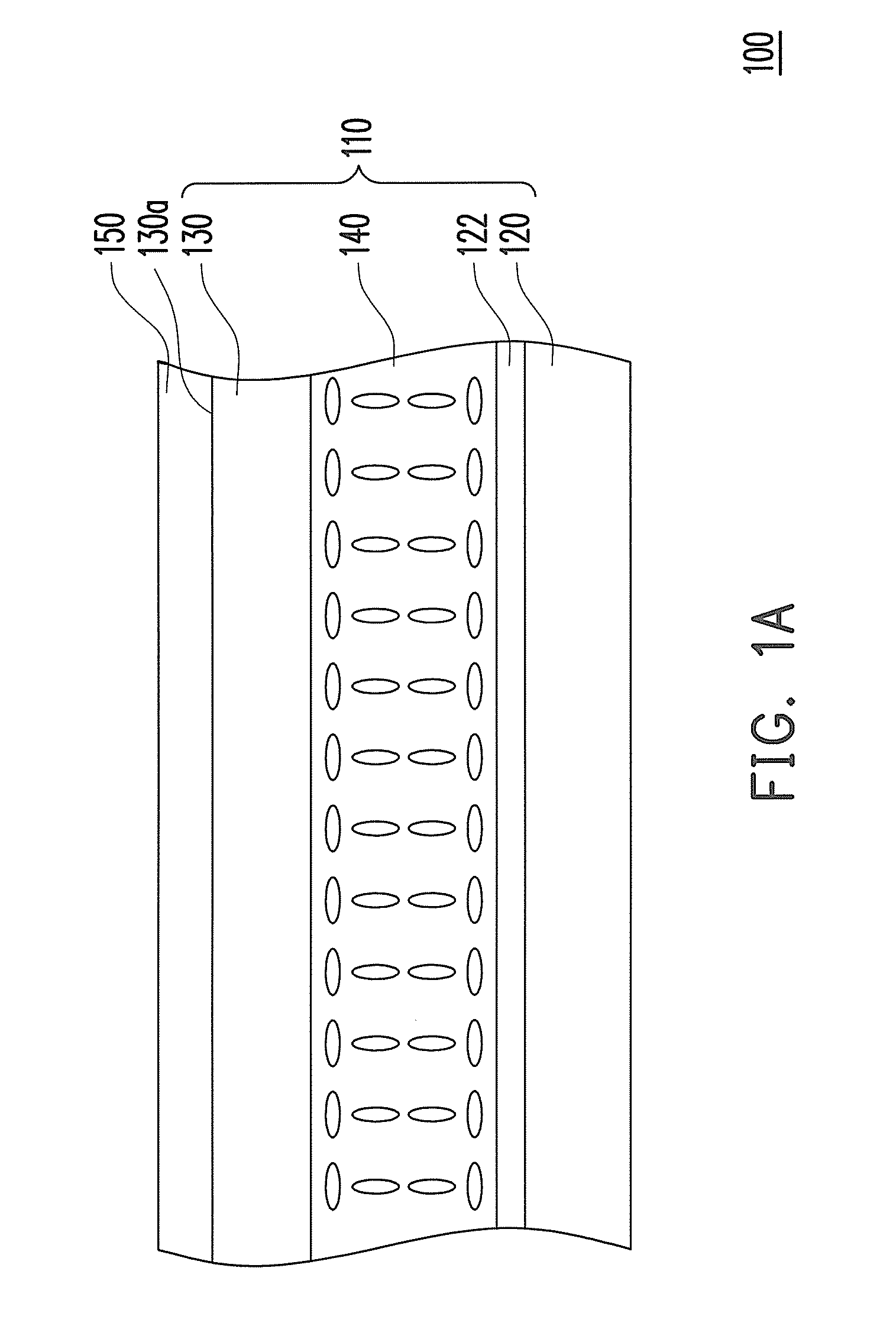
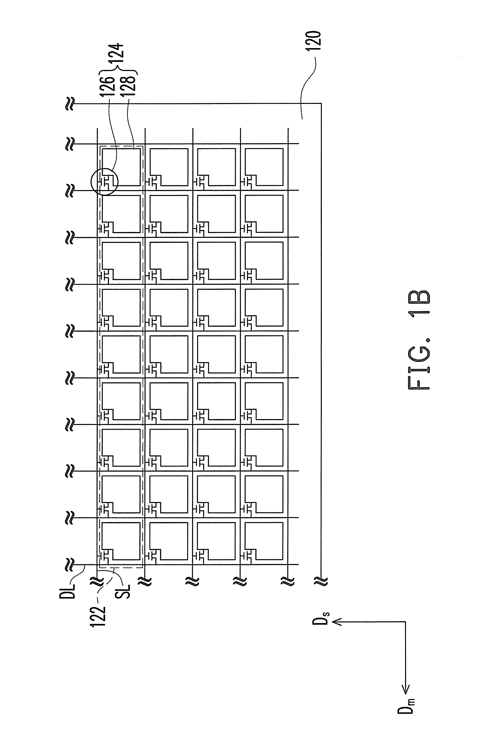
[0057]FIG. 6A is a top view of a sensing element of a sensing display device according to a fourth embodiment of the invention, FIG. 6B is a partial schematic diagram illustrating a configuration showing the relationship of a first electrode and a second electrode of FIG. 6A and a pixel unit array. Referring to FIG. 1A and FIG. 6A, the sensing element 150 is disposed on the pixel units 124, and the sensing element 150 includes a plurality of sensor units, wherein the sensor unit is a mesh-pattern electrode. In the present embodiment, the sensor unit is, for example, the first electrode 162 or the second electrode 172. In detail, in the present embodiment, the sensing element 150 includes a plurality of sensor units 165, which are arranged in a plurality of first serials 160 and a plurality of second serials 170. The first serial 160 is, for example, extended along a first axial direction Dx, and the first serial 160 includes a plurality of first electrodes 160 and a plurality of bri...


PUM


Abstract

A sensing display device including a display panel and a sensing element is provided. The display panel includes at least a plurality of pixel units, and the pixel units are arranged along a primary direction. The sensing element is disposed on the pixel units and includes at least a plurality of sensor units. Each of the sensor units includes a mesh-pattern electrode, and the mesh-pattern electrode includes a plurality of first traces having conductivity. At least one of the first traces is substantially extended along a first direction, wherein a first angle is formed between the first direction and the primary direction, and the first angle is an acute angle.

Description

CROSS-REFERENCE TO RELATED APPLICATION[0001]This application claims the priority benefit of Taiwan application serial no. 99119673, filed on Jun. 17, 2010. The entirety of the above-mentioned patent application is hereby incorporated by reference herein and made a part of this specification.BACKGROUND[0002]1. Field of the Invention[0003]The invention relates to a display device. More particularly, the invention relates to a sensing display device.[0004]2. Description of Related Art[0005]In this information society, people increasingly depend on electronic products. The electronic products such as all-in-one personal computers (AIO PCs), tablet personal computers (tablet PCs), personal digital assistants (PDAs) or smart phones are widely used in daily life. In order to achieve purposes of convenience, compact size and humanity, conventional input devices of many information products such as keyboards and mice have been replaced by touch panels, and a sensing display device or a touch...

Claims


Application Information

Patent Timeline
Patent Type & Authority Applications(United States)
IPC IPC(8): G06F3/041
CPCG02F1/13338G06F3/044G06F3/0412G06F3/0445G06F3/0446
Inventor LIU, PO-YUANWANG, YI-LONGKUO, CHUN-KUHSIEH, MING-LUNCHOU, HUNG-WEN
Owner AU OPTRONICS CORP
Why Eureka
Try Eureka