
User interface transition between camera view and map view

a user interface and map technology, applied in the field of user interface transition between camera view and map view, can solve the problems of users often having difficulty understanding the relevance of maps to users' orientation, initiating navigation in the wrong direction, and the first and most difficult steps of using maps

Active Publication Date: 2011-12-22
QUALCOMM INC
View PDF5 Cites 91 Cited by
  • Summary
  • Abstract
  • Description
  • Claims
  • Application Information

AI Technical Summary

Benefits of technology

[0005]A user interface transition between a camera view and a map view displayed on a mobile platform is provided so as present a clear visual connection between the orientation in the camera view and the orientation in the map view. The user interface transition may be in response to a request to change from the camera view to the map view or vice-versa. The user interface transition may be produced using augmentation overlays for the camera view and map view that identi

Problems solved by technology

One of the first and most difficult steps in using a map is physically orienting oneself in the correct direction.
Incorrect orientation results in initiating navigation in the wrong direction.
While electronic mapping systems using SPS, for example, are useful in determining one's current location, users often have difficulty understanding the maps relevance to the user's orientation.
A heading-up view, however, requires the user to translate between the elements shown on the map (top view) and the elements in front of them (front view), which can difficult because the shapes of the elements do not generally match clearly.
For example, the front face of a building as seen by the viewer may be considerably different than the shape of the building in top view, which may make identification difficult.
Similar to the heading-up view, however, users sometimes find it difficult to understand the relevance of the pie-slice orientation element to the user's actual view as it requires that the user to translate between the elements shown on the map (top view) and the elements in front of them (front view).
Currently there is no way of leveraging the ease of orientation in the augmented reality camera view with the map view.

Method used


Image

  • User interface transition between camera view and map view
  • User interface transition between camera view and map view
  • User interface transition between camera view and map view

Examples


Embodiment Construction

ines included in two sets of horizontal lines and one set of vertical lines.

[0019]FIG. 15 illustrates the top view image with the direction of the sets of horizontal and vertical lines shown with respect to the position of the camera along with the orientation of the camera.

[0020]FIG. 16 illustrates the top view image with the detected edges of the top of building identified and matched to the direction of the sets of horizontal lines.

DETAILED DESCRIPTION

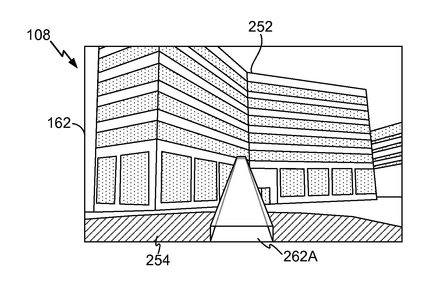
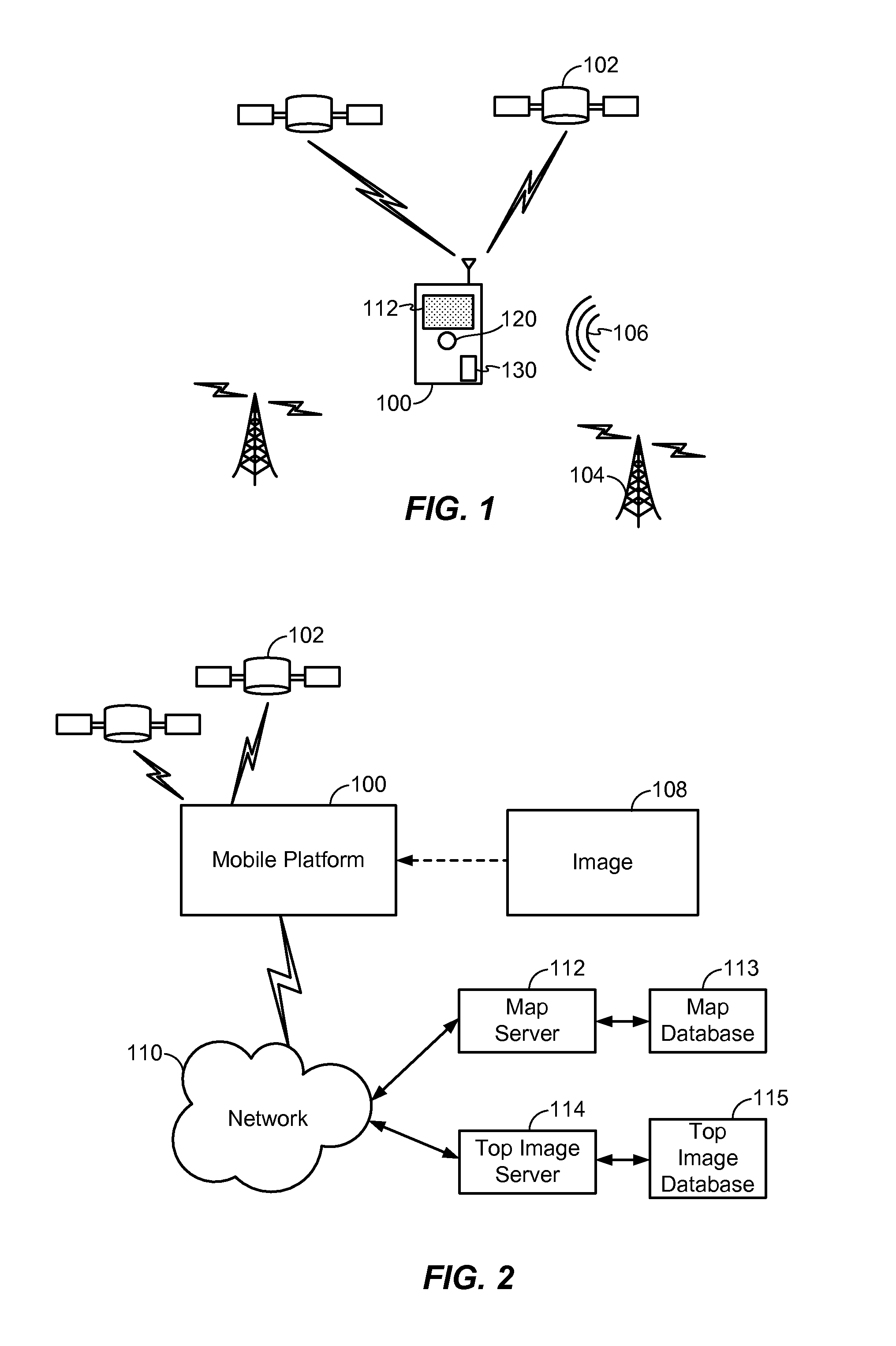
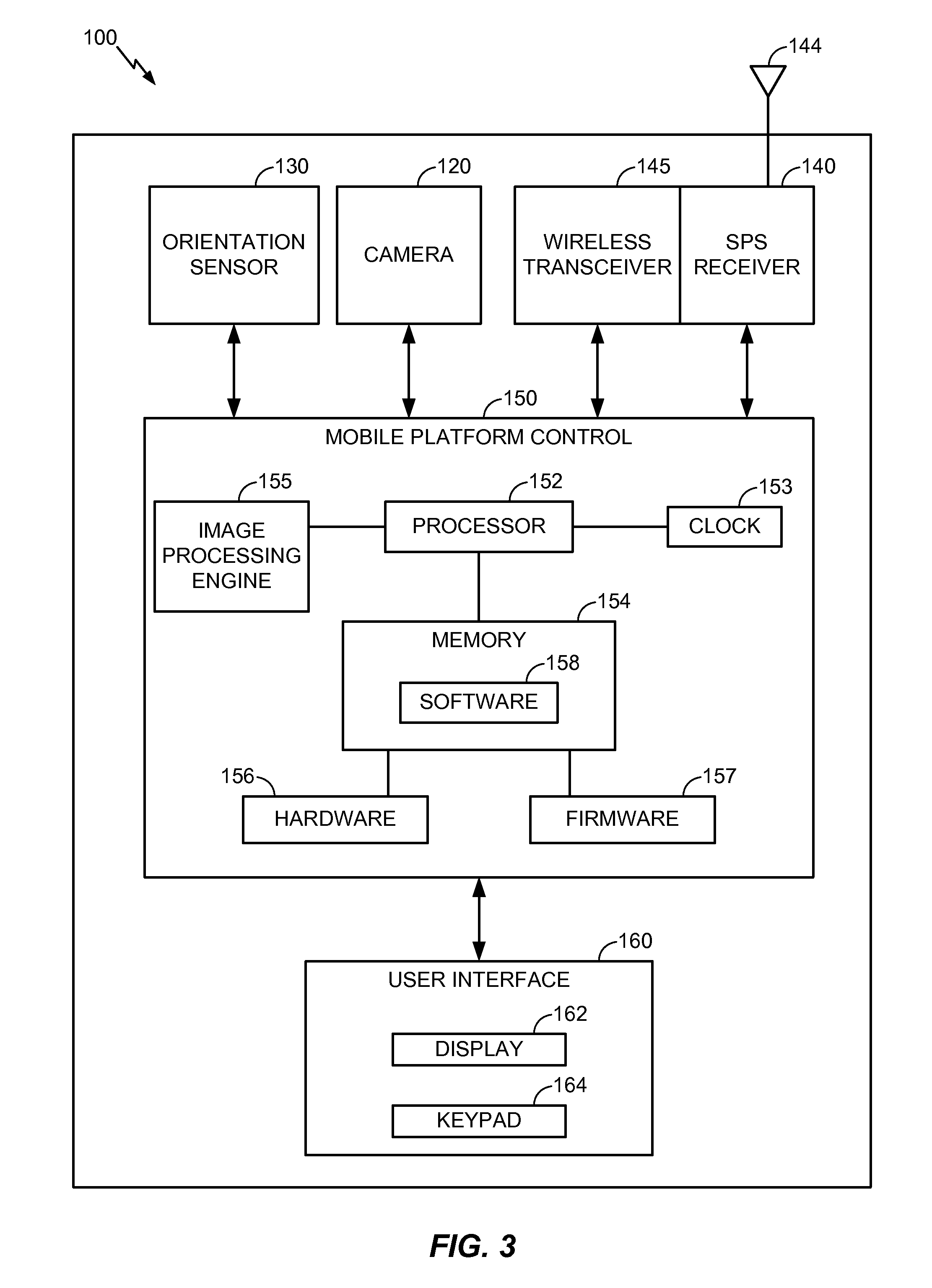
[0021]FIG. 1 illustrates an example of a mobile platform 100 that is capable of displaying a user interface transition between a camera view and a map view to provide a visual connection between the orientations of the two views. In the camera view, a display 162 shows an image of the real-world environment, while in map view the display 162 shows a map that includes the position of the mobile platform 100. The mobile platform 100 displays a user interface transition between the two views with one or more frames showing the changes ...


PUM


Abstract

A user interface transition between a camera view and a map view displayed on a mobile platform is provided so as present a clear visual connection between the orientation in the camera view and the orientation in the map view. The user interface transition may be in response to a request to change from the camera view to the map view or vice-versa. Augmentation overlays for the camera view and map view may be produced based on, e.g., the line of sight of the camera or identifiable environmental characteristics visible in the camera view and the map view. One or more different augmentation overlays are also produced and displayed to provide the visual connection between the camera view and map view augmentation overlays. For example, a plurality of augmentation overlays may be displayed consecutively to clearly illustrate the changes between the camera view and map view augmentation overlays.

Description

BACKGROUND[0001]A common means to determine the location of a device is to use a satellite position system (SPS), such as the well-known Global Positioning Satellite (GPS) system or Global Navigation Satellite System (GNSS), which employ a number of satellites that are in orbit around the Earth. Position measurements using SPS are based on measurements of propagation delay times of SPS signals broadcast from a number of orbiting satellites to an SPS receiver. Once the SPS receiver has measured the signal propagation delays for each satellite, the range to each satellite can be determined and precise navigation information including 3-dimensional position, velocity and time of day of the SPS receiver can then be determined using the measured ranges and the known locations of the satellites.[0002]One of the first and most difficult steps in using a map is physically orienting oneself in the correct direction. Incorrect orientation results in initiating navigation in the wrong directio...

Claims


Application Information

Patent Timeline
IPC IPC(8): G06T15/00H04W4/02H04W4/029
CPCG06T13/80G06T19/006G06T19/003H04W4/029H04W4/02
Inventor WRIGHT, JR., GERALD V.BERNARTE, JOEL SIMBULANKEATING, VIRGINIA WALKER
Owner QUALCOMM INC
Learn More