

Uplink power control method for mobile communication system
a technology of mobile communication system and power control method, which is applied in power management, digital transmission, electrical equipment, etc., can solve the problems of severe power limitations of the transmitter of the user equipment, low power efficiency, and low transmit power, so as to improve the transmission quality of uplink and mitigate inter-cell interference
- Summary
- Abstract
- Description
- Claims
- Application Information
AI Technical Summary
Benefits of technology
Problems solved by technology
Method used
Image

Examples
first embodiment
[0045]FIG. 3 is a flowchart illustrating the power control method of a UE, according to the present invention.
[0046]Referring to FIG. 3, the UE 20 receives the parameters necessary for controlling its transmit power from the base station, in step 300. In order to define the parameters, it is necessary to derive a power control equation for per-layer power control. The per-layer power control equation for the LTE-A system should be configured such that the characteristics of the layer mapper 201 is well reflected, while the influence of the per-layer power control to each codeword does not defy the aim of the power control in the LTE system. Taking this into consideration, the per-layer power control equation for the LTE-A can be expressed as Equation (7) below:
PPUSCH(i)=min{PCMAX,∑l=1LPPUSCH_layer(i,l)}[dBm]PPUSCH_layer(i,l)=min{PCMAX_layer(l),PPUSCH_layer-CALC(i,l)}[dBm]PPUSCH_layer-CALC(i,l)=10log10(MPUSCH(i))+PO_PUSCH(j)+α(j)·PL+f(i)+ΔTF(i,CW(l))+Δlayer(l)[dBm](7)
where PCMAX, MPU...
second embodiment
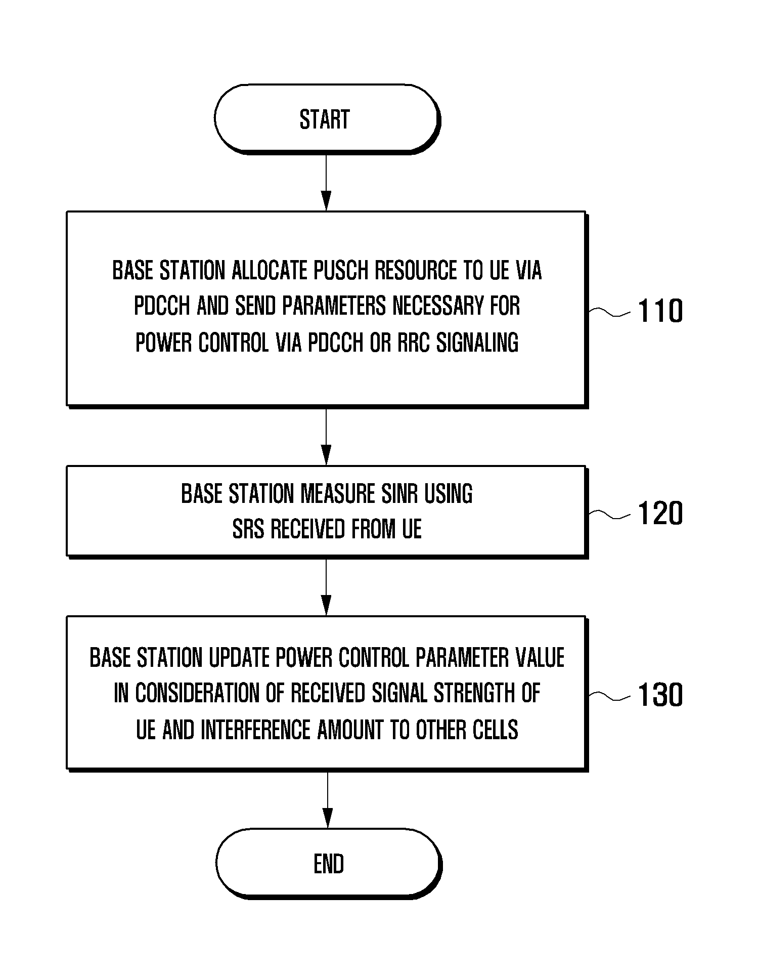
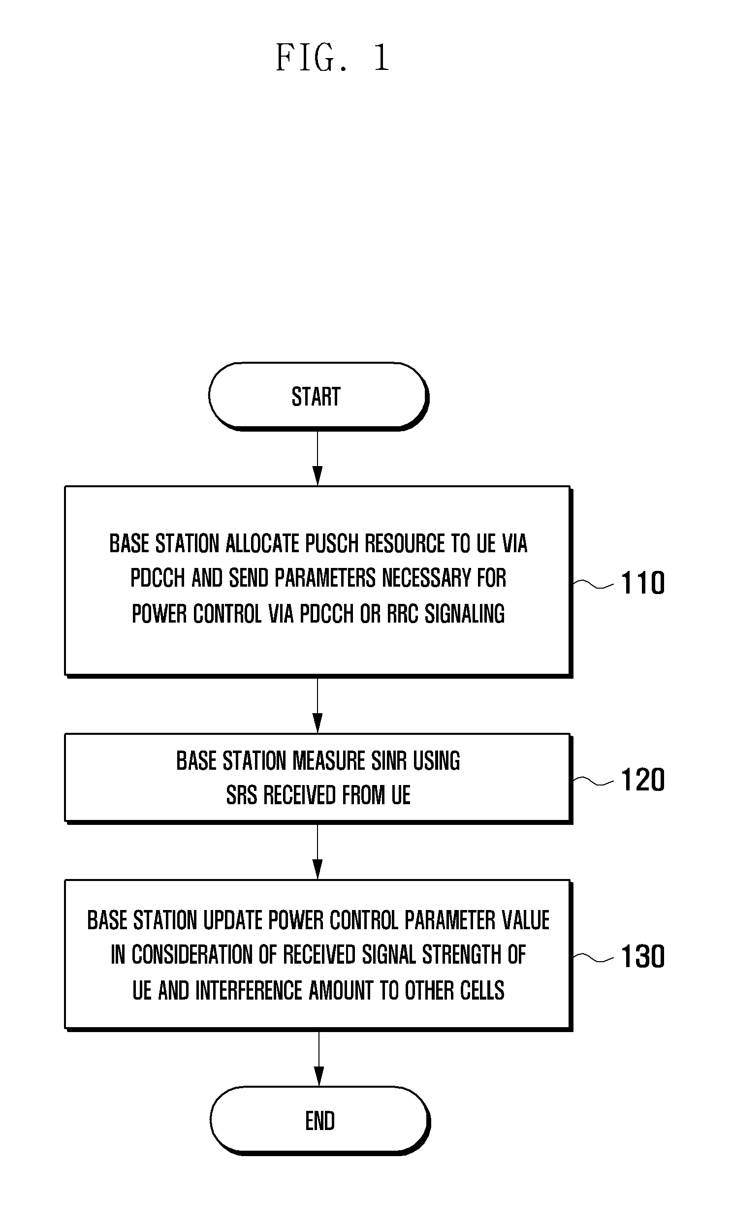
[0059]In the LTE-A system, according to the present invention, the base station follows the power control procedure of FIG. 1, and the parameters necessary for power control are transmitted for use in Equation (7).
[0060]A description is made of a per-antenna power control method of the transmitter of a UE based on the parameters related to the uplink power control and TBS information that are transmitted by the base station, according to the third and fourth embodiments of the present invention.
[0061]FIG. 5 is a block diagram illustrating a configuration of a UE transmitter, according to third, fourth, fifth, sixth, and seventh embodiments of the present invention.
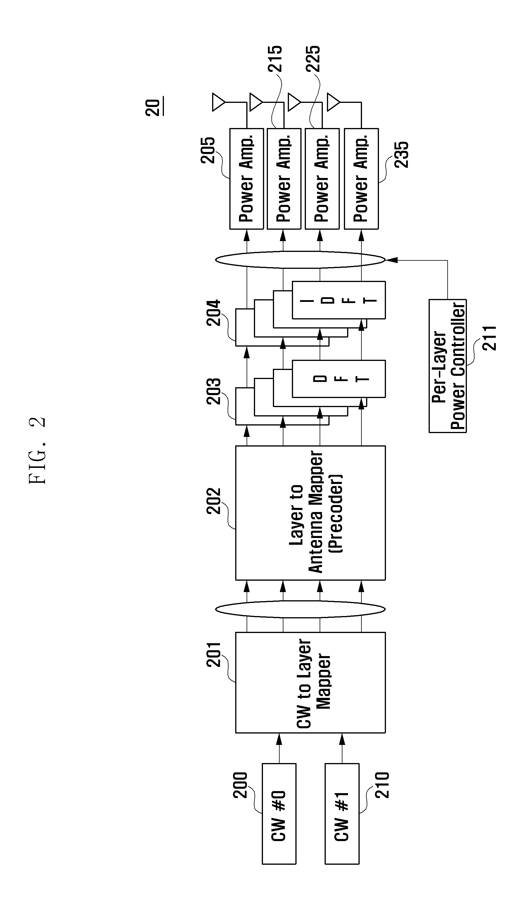
[0062]As shown in FIG. 5, a UE 50 includes a first codeword generator 500, a second codeword generator 510, a layer mapper 501, an antenna mapper 502, a DFT performer 503, a IDFT performer 504, a plurality of PAs 505, 525, 525, and 535, and a per-antenna power controller 514.
[0063]The first codeword generator 500 generates...
third embodiment
[0064]FIG. 6 is a flowchart illustrating the power control method of a UE, according to the preset invention.
[0065]Referring to FIG. 6, the UE 50 receives the parameters necessary for its transmit power control from the base station. In order to define the parameters, it is necessary to derive a power control equation for per-layer power control. The per-layer power control equation for the LTE-A system should be configured such that the characteristics of the antenna mappers 501 and 502 are well reflected, while the influence of the per-antenna power control to each codeword does not defy the aim of the power control in the LTE system. In consideration of this, the per-antenna power control equation for LTE-A can be expressed as Equation (10) below:
PPUSCH(i)=min{PCMAX,∑n=1NPPUSCH,ant(i,n)}[dBm]PPUSCH_ant(i,n)=min{PCMAX_ant(n),PPUSCH_ant-CALC(i,n)}[dBm]PPUSCH_ant-CALC(i,n)=10log10(MPUSCH(i))+PO_PUSCH(j)+f(i)+ΔTF(i,CWI(PMI,n))+ΔC-to-A(PMI,n)+α(j)PL(n)[dBm](10)
where PCMAX, MPUSCH(i), ...
PUM
 Abstract
Description
Claims
Application Information