Developing device and image formation apparatus

a technology of developing device and image formation apparatus, which is applied in the direction of electrographic process apparatus, instruments, optics, etc., can solve the problems of uneven surface of developer, imbalance between developer amounts, degradation of developing performance, etc., and achieve the effect of preventing degradation of developing performance and downsizing the apparatus

Inactive Publication Date: 2011-12-22
KONICA MINOLTA BUSINESS TECH INC
View PDF6 Cites 32 Cited by
  • Summary
  • Abstract
  • Description
  • Claims
  • Application Information

AI Technical Summary

Benefits of technology

[0027]One aim of the present invention is to provide a developing device and an image formation apparatus t...

Problems solved by technology

With such a structure for circulation, developer often accumulates in the communication passages, which makes the surface of the developer uneven.
Such an uneven surface level of the developer leads to an imbalance between the amounts of the developer at both edges of the developing roller in the direction of the axis thereof.
This is problematic because, for example, there is a risk of degradation in the developing performance at one edge of the developing roller that is provided with a smaller amount of developer than the other edge.
Shortening the width of the housing means decreasing the capacity of the housing, and thus it is necessary to decrease the amount of the developer to be housed therein.
However, the flow of the developer becomes more turbulent as the rotation speed of the transport screw increases, and the transport amount per unit of the developer does not change linearly according to the change of the rotation speed of the transport screw.
Thus, it is difficult to increase the circulation speed of the developer simply by increasing the rotation speed of the transport screw.
Furt...

Method used


Image

  • Developing device and image formation apparatus
  • Developing device and image formation apparatus
  • Developing device and image formation apparatus

Examples


embodiment 1

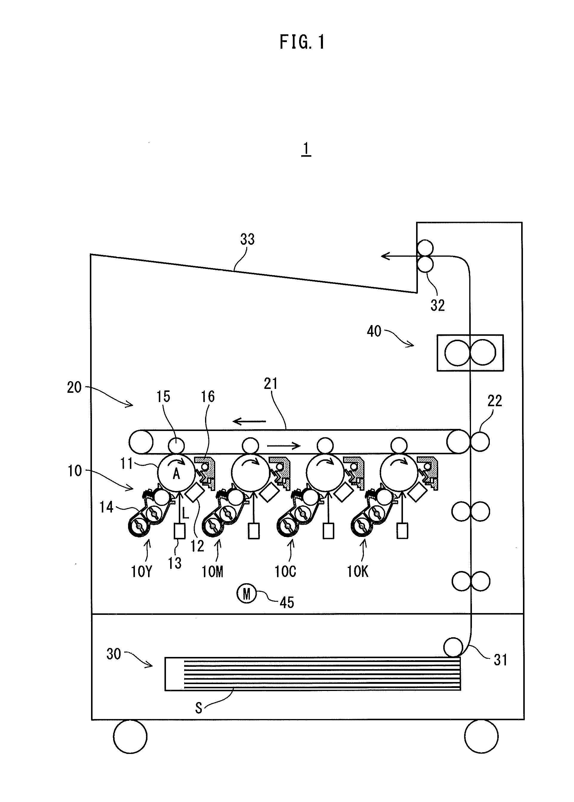
[0046]FIG. 1 is a schematic diagram showing an overall structure of a printer 1 pertaining to Embodiment 1.

[0047]As shown in the drawing, the printer 1 forms images by a well-known electrophotographic method. The printer 1 includes, an image processing unit 10, an intermediate transfer unit 20 provided with an intermediate transfer belt 21, a paper feed unit 30, and a fusing unit 40. The printer 1 is capable of performing color printing based on job requests from an external terminal device (not depicted) received via a network (such as a LAN).

[0048]The image processing unit 10 includes image creating units 10Y, 10M, 10C, and 10K corresponding respectively to colors of yellow (Y), magenta (M), cyan (C), and black (K). The image creating unit 10Y includes a photosensitive drum 11, and a charger 12, an exposing unit 13, a developing unit 14, a first transfer roller 15, and a cleaner 16, which are arranged around the photosensitive drum 11.

[0049]The charger 12 electrically charges the ...

embodiment 2

[0192]In Embodiment 1 above, the pitch of the feed screw 52 and the pitch of the stirring screw 53 are the same. In Embodiment 2, the pitches are different. This is the difference from Embodiment 1. In the following, the same explanation as for Embodiment 1 is omitted, and the same components are identified with the same reference signs.

[0193]FIG. 12 shows the structures of the feed screw 201 and the stirring screw 202 to be provided in the developing unit 200 of Embodiment 2. FIG. 13 is a side view showing the structure of a mechanism for transmitting driving force to the feed screw 201 and the stirring screw 202.

[0194]As shown in FIG. 12, P123 is satisfied, where P1 denotes the pitch of the section of the spiral blade of the feed screw 201 within the area M1, P2 denotes the pitch of the section of the spiral blade of the stirring screw 202 within the area M2, and P3 denotes the pitch of the section of the spiral blade of the stirring screw 202 within the area M3.

[0195]As also show...


PUM


Abstract

A developing device comprising: a first transport member disposed in a first transport passage and configured to rotate and thereby transport developer; a second transport member disposed in a second transport passage and configured to rotate and thereby transport the developer; and a developer carrier configured to carry the developer supplied from the first transport passage, wherein the second transport passage is composed of an upstream section and a downstream section, the second transport passage communicates with the first transport passage via a first communication passage and a second communication passage, the upstream section is configured to receive refill toner, and V1<V2<V3, where V1 denotes an average transport speed of the first transport member, V2 denotes an average transport speed of an upstream section of the second transport member, and V3 denotes an average transport speed of a downstream section of the second transport member.

Description

[0001]This application is based on application No. 2010-140708 filed in Japan, the contents of which are hereby incorporated by reference.BACKGROUND OF THE INVENTION[0002](1) Field of the Invention[0003]The present invention relates to a developing device and an image formation apparatus provided with the same.[0004](2) Description of the Related Art[0005]Image formation apparatuses, which include copiers and printers, are provided with a developing device that develops, by using developer, an electrostatic latent image formed on an image carrier such as a photosensitive drum.[0006]A developing device usually includes a developing roller for carrying developer, and a circulation passage for circulating the developer with the aid of, for example, a transport screw provided with a spiral blade.[0007]The developing roller faces the photosensitive drum, and develops an electrostatic latent image formed on the photosensitive drum, by using developer carried thereby and toner.[0008]In man...

Claims


Application Information

Patent Timeline
IPC IPC(8): G03G15/08
CPCG03G2215/0802G03G15/0887G03G15/0893
Inventor OKAZAKI, FUTOSHIISHIDA, HIROFUMI
Owner KONICA MINOLTA BUSINESS TECH INC
Why Eureka
Try Eureka