
Perforated web product

a perforated web and product technology, applied in the field of perforated web products, can solve the problems of imposing speed limitations, affecting the overall quality, and affecting the overall reliability, so as to facilitate the removal of sheets, reduce manufacturing costs, and enhance reliability.

Active Publication Date: 2011-12-22
THE PROCTER & GAMBLE COMPANY
View PDF3 Cites 60 Cited by
  • Summary
  • Abstract
  • Description
  • Claims
  • Application Information

AI Technical Summary

Benefits of technology

The present patent provides perforating apparatuses and methods, as well as perforated web products, that overcome the problems of current manufacturing methods and provide enhanced reliability, lower manufacturing costs, greater flexibility, and higher perforation quality. The perforated web products have repeating lines of perforation that each comprise at least a plurality of individual perforations, which may be printed with liquid. These improvements result in a more practical and aesthetically desirable product for the consumer.

Problems solved by technology

While this conventional operation has been widely adopted, there are a number of well known drawbacks in terms of the overall reliability, manufacturing costs, flexibility, and perforation quality.
Among the drawbacks is the fact that the interaction of the moving blade and the stationary anvil is known to impose a speed limitation since vibrations produced at high speeds adversely affect the overall quality of the perforations formed in a web.
Further, the vibrations caused by the interaction of the moving blade and stationary anvil may result in costly web breaks or equipment malfunctions requiring a shutdown of the manufacturing operation.
For instance, it is known that the teeth on the moving blade become dull or broken after a period of use.
This not only will result in an inferior and unacceptable level of perforation quality, but it will also require a temporary shutdown of the manufacturing operation to replace the moving blade and to discard inferior product produced immediately prior to shutdown.
As will be appreciated, this results in unacceptable waste and significantly increased manufacturing costs.
In addition, another drawback to conventional equipment has been the inability to quickly change from one perforation pattern format (or sheet length) to another without significant down time for the changeover.
While the changeover is occurring, there is obviously no product being produced and personnel must be actively engaged in implementing the changeover, all of which leads to significantly increased manufacturing costs.
While various approaches have been suggested, none have offered the requisite level of perforation quality that would result in a fully acceptable product.

Method used


Image

  • Perforated web product
  • Perforated web product
  • Perforated web product

Examples


Embodiment Construction

[0027]As used herein, the term “machine direction” (MD) means the direction of travel of a web through any processing equipment. The term “cross direction” (CD) is orthogonal and coplanar thereto. The term “Z-direction” is orthogonal to both the machine and cross directions.

[0028]The various embodiments of the present disclosure described in detail below provide several non-limiting examples of perforating apparatuses, methods, and several distinct perforated web products having improved features which result in enhanced reliability, lower manufacturing costs, greater flexibility, and higher perforation quality. With regard to these non-limiting examples, the described apparatuses and methods make it possible to effectively and efficiently design and produce a variety of different perforated web products having enhanced practical and aesthetic desirability.

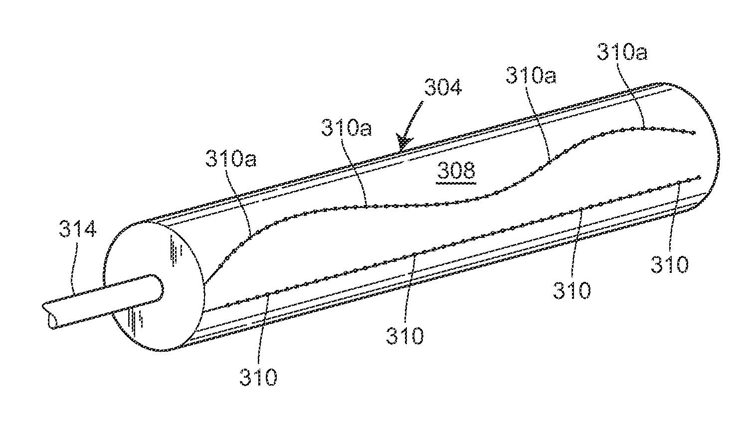
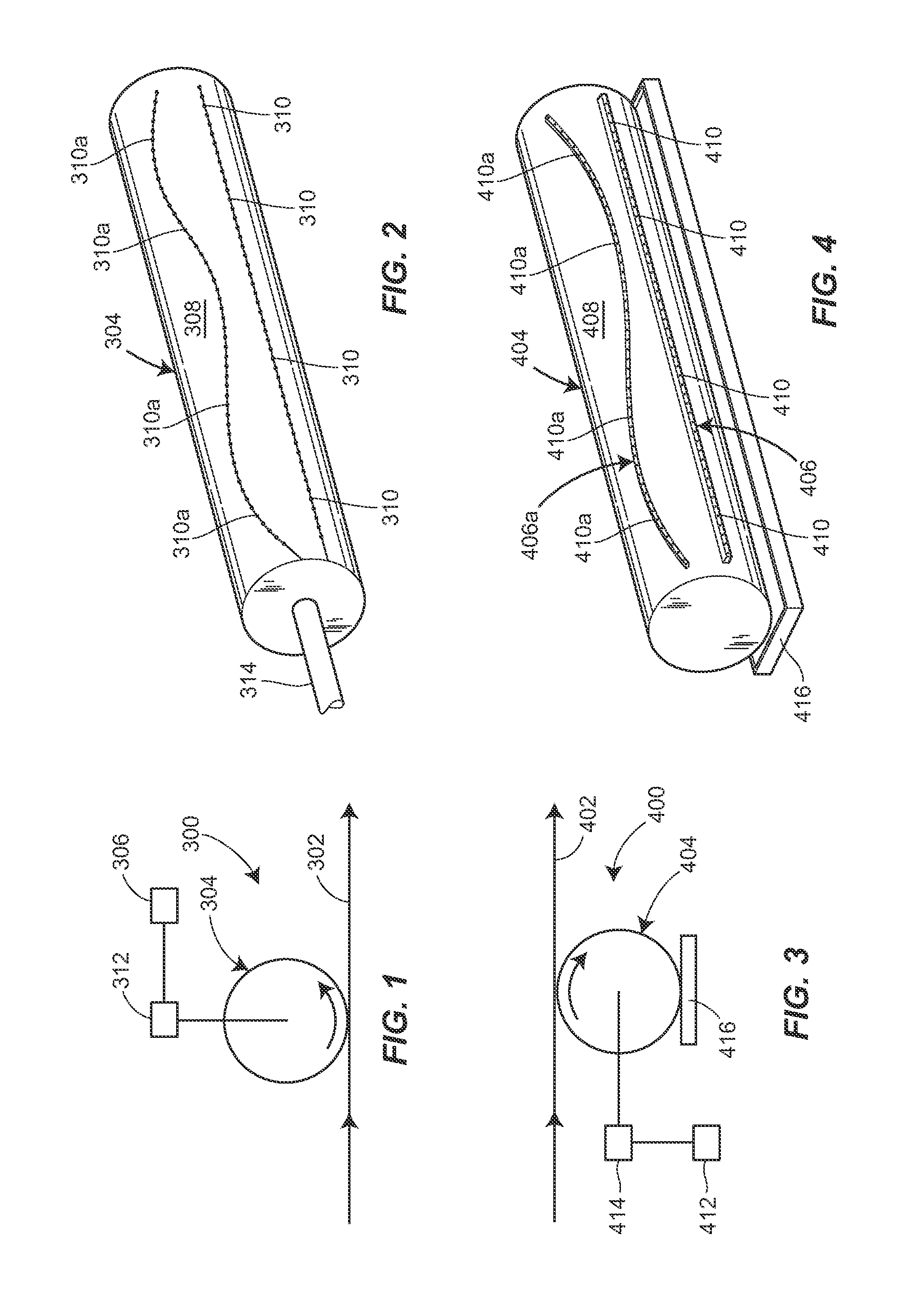
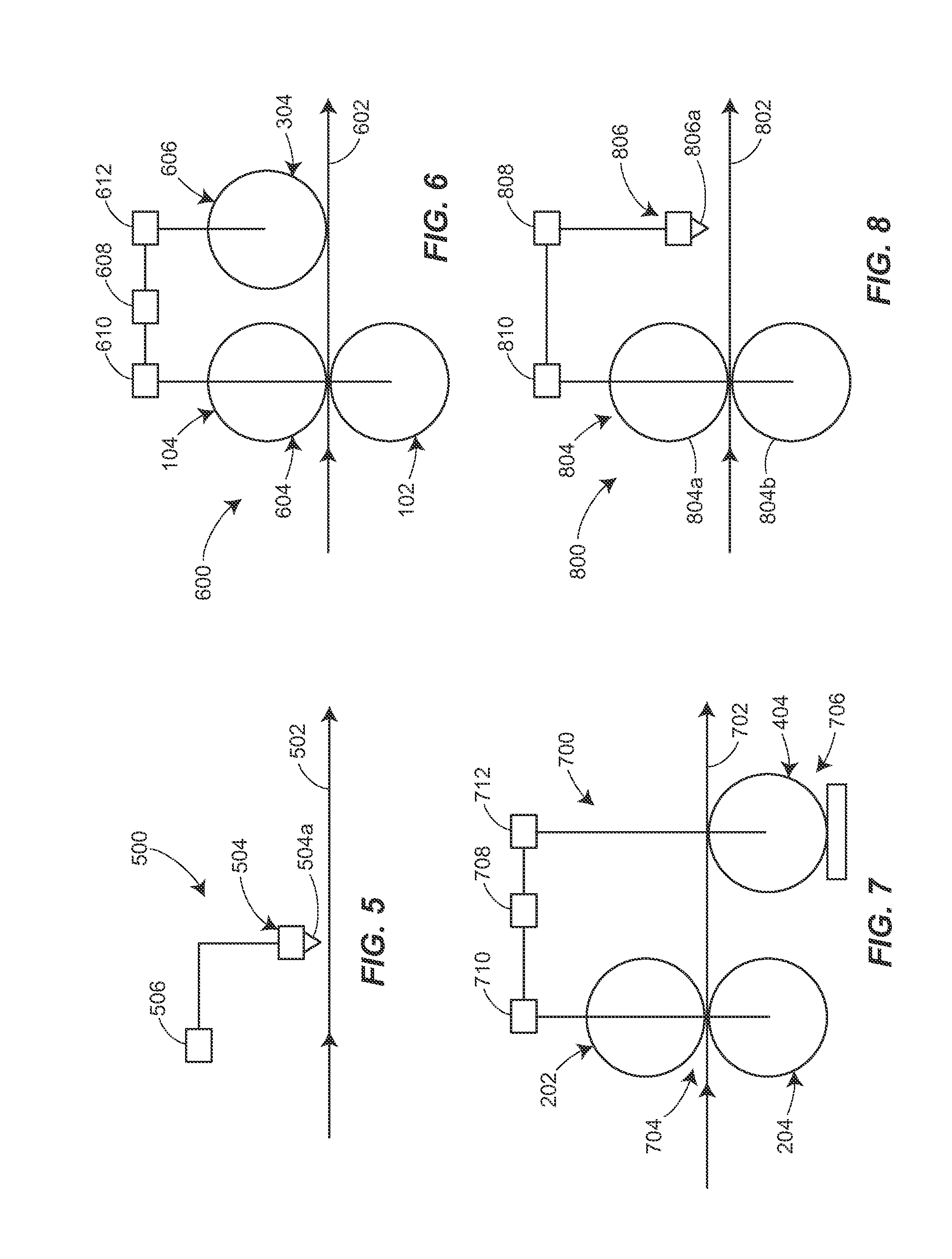
[0029]Referring to FIG. 1, an apparatus 300 for perforating a web 302 is illustrated which includes a liquid printing device 304...


PUM

PropertyMeasurementUnit
lengthaaaaaaaaaa
lengthaaaaaaaaaa
lengthaaaaaaaaaa

Abstract

Web products are disclosed which include forming selected perforation designs and patterns. The perforation designs and patterns can be formed in linear or nonlinear fashion, can extend in the cross direction or the machine direction and can be formed to complement or match an embossed or printed design on the web. The perforation designs and patterns can be formed utilizing various mechanical perforating techniques.

Description

FIELD OF THE INVENTION[0001]The present invention relates generally to perforated web products having various capabilities, characteristics and features. More particularly the present invention relates to web products of this type having significantly improved reliability, lower manufacturing costs, greater flexibility, and higher perforation quality.BACKGROUND OF THE INVENTION[0002]For many years, it has been well known to perforate products manufactured from webs such as paper towels, bath tissue and the like to thereby facilitate the removal of sheets from a roll by tearing. There have been proposed a variety of types of mechanical apparatus and numerous different methods for forming the perforations for these products. Typically, a moving blade has been utilized to perforate a web as it passes between the moving blade and a stationary anvil wherein the moving blade extends perpendicular to the direction of travel of the web.[0003]While this conventional operation has been widely...

Claims


Application Information

Patent Timeline
Patent Type & Authority Applications(United States)
IPC IPC(8): B32B29/00B26F1/00
CPCA47K10/16B26F1/20B26F1/22B26F1/24B32B3/266B32B29/005Y10T428/24B32B2262/067B32B2305/70B32B2307/582Y10T428/15Y10T428/24273B32B2250/26B32B5/02B32B5/26B32B2262/0223B32B2262/0253B32B2262/0261B32B2262/0276B32B2262/04B32B2262/062B32B2262/101B32B2307/546B32B2307/726B32B2307/75B32B2432/00B32B2555/00
Inventor MCNEIL, KEVIN BENSONSINGER, JAMES MICHAEL
Owner THE PROCTER & GAMBLE COMPANY
Learn More