Storage system

a storage system and storage technology, applied in the field of storage systems, can solve the problems of high-capacity storage systems, data to be stored has increased day by day, and the need for high-capacity storage systems, and achieve the effect of inhibiting the decrease of the performance of the system

Inactive Publication Date: 2011-12-22
NEC CORP +1
View PDF6 Cites 25 Cited by
  • Summary
  • Abstract
  • Description
  • Claims
  • Application Information

AI Technical Summary

Benefits of technology

[0018]With the configurations as described above, the present invention can realize a storage system that contr

Problems solved by technology

Because data to be stored has increased day by day and the amount thereof has become huge, a high-capacity storage system is required.
On the other hand, although having high redundancy as described above, the content address storage system also needs a replication of stored data.
However, in a case that a huge amo

Method used


Image

  • Storage system
  • Storage system
  • Storage system

Examples


first exemplary embodiment

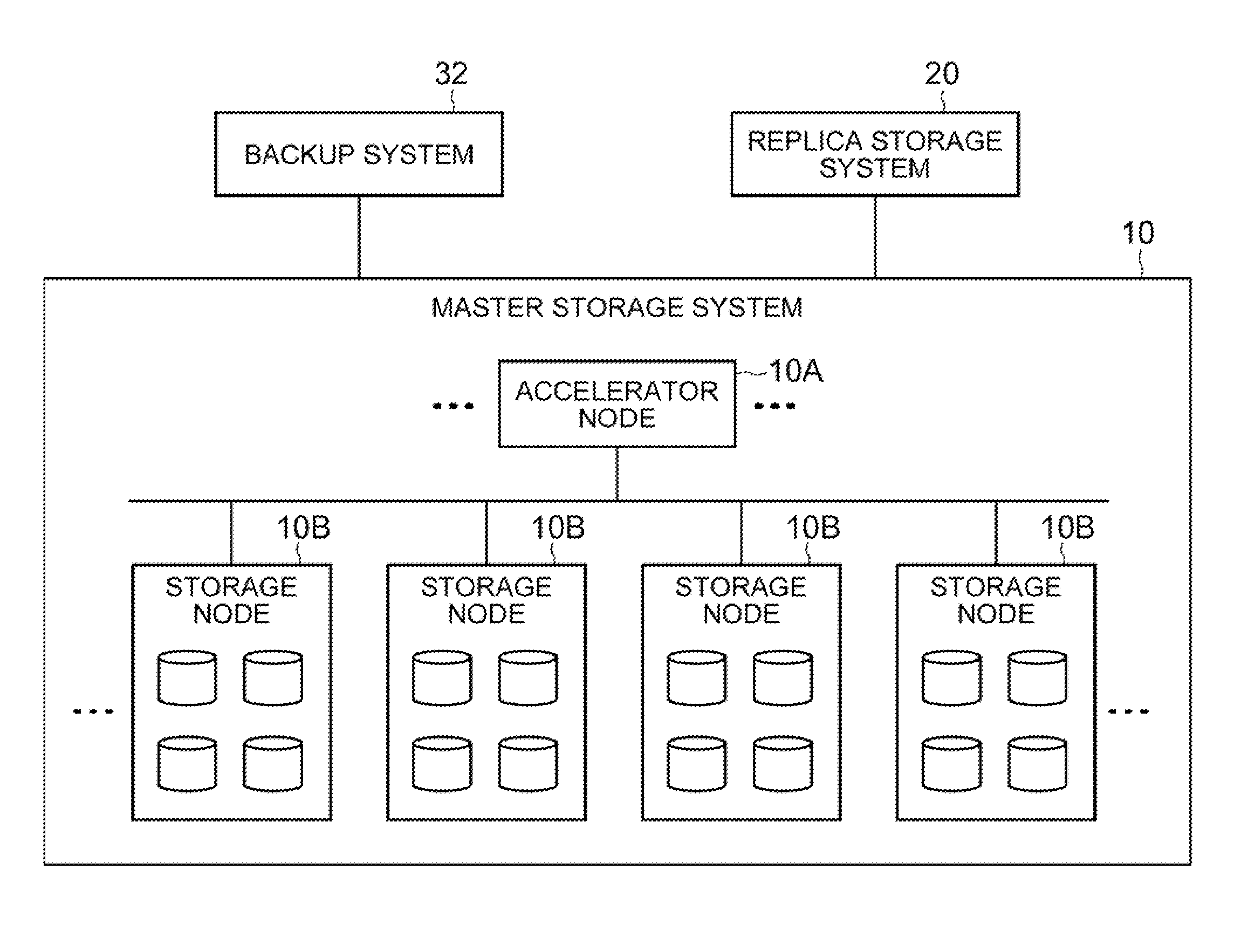
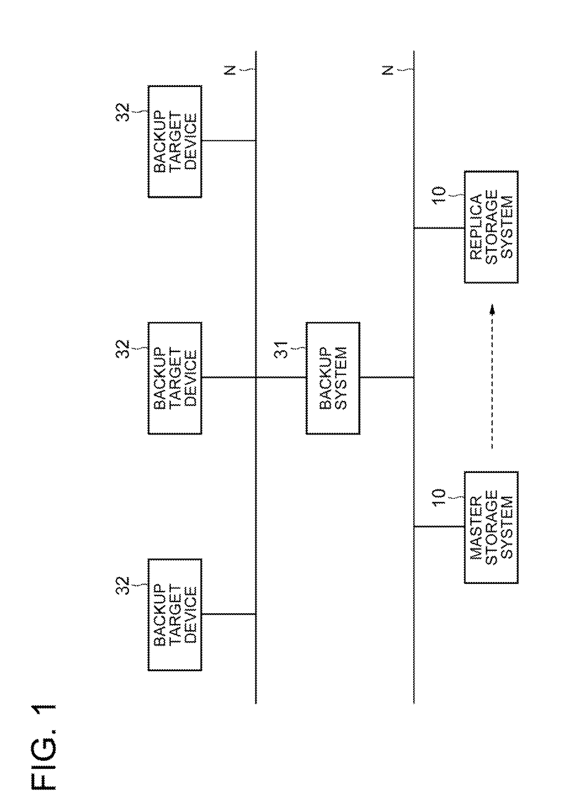
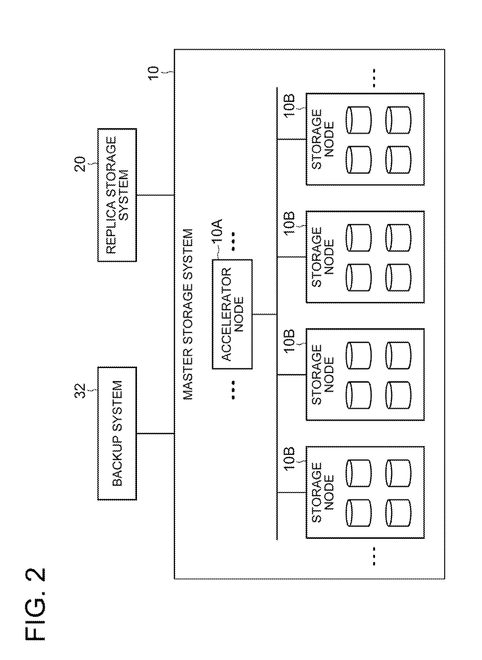
[0034]A first exemplary embodiment of the present invention will be described with reference to FIGS. 1 to 14. FIG. 1 is a block diagram showing a configuration of a whole system. FIG. 2 is a block diagram showing a schematic configuration of a storage system. FIGS. 3 and 4 are views showing an aspect of storage of data into the storage system. FIG. 5 is a view showing an example of metadata to be stored. FIGS. 6 and 7 are views showing a configuration for executing replication of the storage system. FIGS. 8 and 9 are flowcharts each showing an operation of the storage system. FIGS. 10 to 14 are views showing aspects of data processing in the storage system.

[0035]This exemplary embodiment shows a specific example of a storage system disclosed in a second exemplary embodiment described later. Below, a case of configuring the storage system by connecting a plurality of server computers will be described. However, the storage system of the present invention is not limited to being conf...

second exemplary embodiment

[0109]Next, a second exemplary embodiment of the present invention will be described with reference to FIG. 15. FIG. 15 is a function block diagram showing a configuration of a storage system of this exemplary embodiment. In this exemplary embodiment, the storage system will be schematically described.

[0110]As shown in FIG. 15, a storage system of this exemplary embodiment includes: a copy source storage system I configured to store a copy source file system 2 that includes storage data and key data referring to the storage data and being unique depending on the data referred to thereby; and a copy destination storage system 3 configured to become a copy destination of the copy source file system stored in the copy source storage system.

[0111]Then, the storage system also includes: a copy processing means 5 configured to copy the copy source file system 2 stored in the copy source storage system 1 into the copy destination storage system 3, and form a copy destination file system 4 ...


PUM


Abstract

A system includes: a copy processing means configured to copy a copy source file system that includes storage data and key data referring to the storage data and being unique depending on the data, from a copy source storage system storing the copy source file system into a copy destination storage system, thereby forming a copy destination file system; and an update data specifying means configured to compare the key data within the copy source file system with the key data within the copy destination file system and specify, as update data, the storage data within the copy source file system referred to by the key data within the copy source file system, the storage data not existing in the copy destination file system. The copy processing means is configured to copy the update data stored within the copy source file system into the copy destination file system.

Description

TECHNICAL FIELD[0001]The present invention relates to a storage system, and specifically, relates to a storage system that distributes and stores data into a plurality of storage devices.BACKGROUND ART[0002]In recent years, as computers have developed and become popular, various kinds of information are put into digital data. As a device for storing such digital data, there is a storage device such as a magnetic tape and a magnetic disk. Because data to be stored has increased day by day and the amount thereof has become huge, a high-capacity storage system is required. Moreover, it is required to keep reliability while reducing the cost for storage devices. In addition, it is required that data can be retrieved later with ease. As a result, such a storage system is desired that is capable of automatically realizing increase of the storage capacity and performance thereof, that eliminates a duplicate of storage to reduce the cost for storage, and that has high redundancy.[0003]Under...

Claims


Application Information

Patent Timeline
IPC IPC(8): G06F17/30
CPCG06F3/0617G06F3/067G06F3/065
Inventor HIRONAGA, RYUJINAGANE, SATORU
Owner NEC CORP
Why Eureka
Try Eureka