Method and device for reducing signal peak value and transmitting device

a signal peak value and transmitting device technology, applied in the field of wireless communication technology, can solve the problems of in-band distortion and out-of-band power radiation of signals, increased difficulty and cost in implementing systems, and restricted further development and application of ofdm technology, so as to improve the overall performance of systems and improve the ability to prevent interferen

Inactive Publication Date: 2010-01-28
HUAWEI TECH CO LTD
View PDF5 Cites 20 Cited by
  • Summary
  • Abstract
  • Description
  • Claims
  • Application Information

AI Technical Summary

Benefits of technology

[0023]In the embodiments of the present invention, a weight of each sub-carrier is set according to a peak clipping weight factor (the peak clipping weight factor includes, but is not limited to, an encoding mode, a constellation mapping mode, a transmit power, and a receiving quality class) or a fr

Problems solved by technology

As a result, the difficulty and cost for implementing the system are increased, and the further development and application of the OFDM technology are restricted.
The peak clipping and amplitude limiting solution is easier to implement, but caus

Method used


Image

  • Method and device for reducing signal peak value and transmitting device
  • Method and device for reducing signal peak value and transmitting device
  • Method and device for reducing signal peak value and transmitting device

Examples


embodiment 1

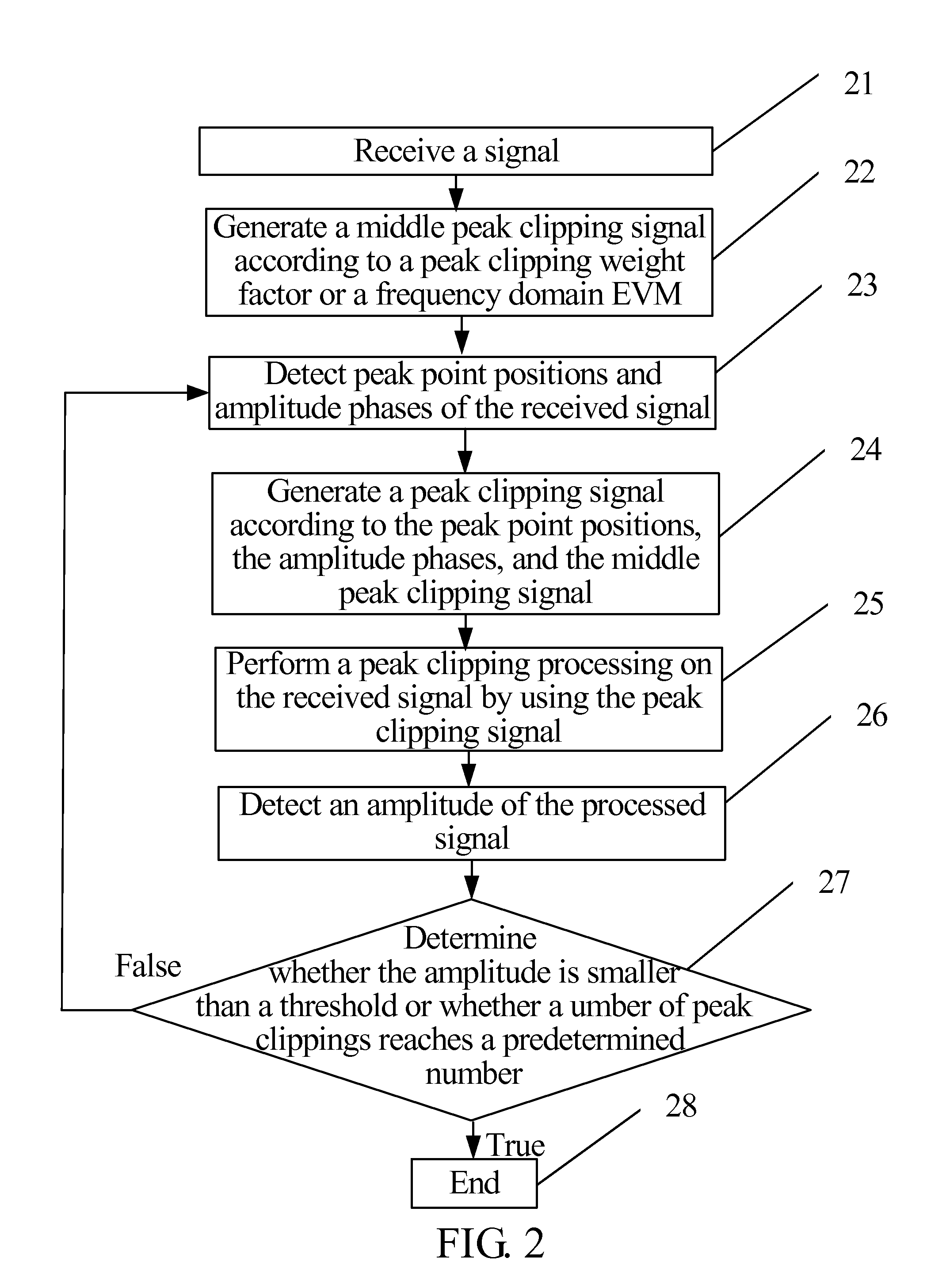
[0040]In this embodiment, the method for reducing a signal peak value is described with reference to FIG. 2.

[0041]In Step 21, a signal is received.

[0042]In Step 22, a middle peak clipping signal is generated according to a peak clipping weight factor or a frequency domain EVM.

[0043]In Step 23, peak point positions and amplitude phases of the received signal are detected.

[0044]In Step 24, a peak clipping signal is generated according to the peak point positions, the amplitude phases, and the middle peak clipping signal.

[0045]In Step 25, a peak clipping processing is performed on the received signal by using the peak clipping signal.

[0046]In Step 26, the amplitude of the processed signal is detected.

[0047]In Step 27, it is determined whether the amplitude is lower than a threshold or whether a number of peak clippings reaches a predetermined number, and if a determination result is true, Step 28 is performed in which the received signal after the peak clipping processing is output and...

embodiment 2

[0074]In this embodiment, the method for reducing a signal peak value is described with reference to FIG. 5.

[0075]In Step 51, a signal is received.

[0076]In Step 52, a weight of each sub-carrier in a symbol is obtained.

[0077]The weight of the sub-carrier may be obtained based on the following equation:

wj=∑i=1Iwj,iorwj=∏i=1Iwj,i

[0078]where wj denotes a weight of the jth sub-carrier (wj≧0); and wj,i denotes a weight of the jth sub-carrier under an ith peak clipping weight factor.

[0079]The weight of the sub-carrier may also be obtained based on the following equation:

w1EVM1≈w2EVM2≈…≈wNEVMN

[0080]where EVM1, . . . , EVMN denote upper limits of frequency domain EVMs of the sub-carrier 1, . . . , the sub-carrier N; and w1, . . . , wN denote peak clipping weights of the sub-carrier 1, . . . , the sub-carrier N. The method for setting a weight of a peak clipping weight factor can be referred to that described in Step 32.

[0081]In Step 53, an ideal peak clipping signal is obtained. The ideal pe...

embodiment 3

[0089]In this embodiment, a device for reducing a signal peak value is described.

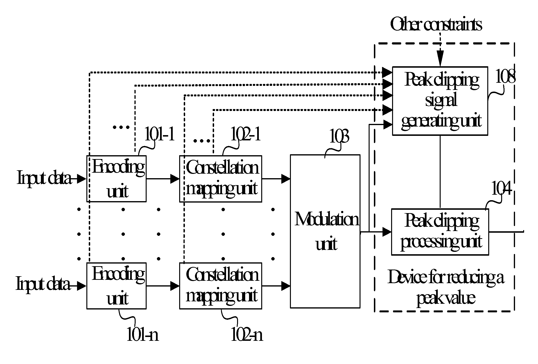
[0090]As shown in FIG. 6, the device for reducing a signal peak value includes:

[0091]a receiving unit, adapted to receive a signal or a signal returned by a peak clipping processing unit;

[0092]a peak clipping signal generating unit, adapted to generate a peak clipping signal according to a peak clipping weight factor or a frequency domain EVM and the received signal of the receiving unit; and

[0093]the peak clipping processing unit, adapted to: perform a peak value reduction processing on the received signal according to the peak clipping signal; determine whether an amplitude of the processed signal is lower than a threshold or whether a number of peak clippings reaches a predetermined number; and if the amplitude is lower than the threshold or the number of peak clippings reaches the predetermined number, output the signal and end the process; otherwise, output the signal to the receiving unit.

[0094]FI...


PUM


Abstract

A method and a device for reducing a signal peak value are adapted to solve a problem that overall performance of a system is significantly degraded caused by allocating a same weight to each sub-carrier so as to averagely distribute a peak clipping noise to each sub-carrier. The method includes: receiving a signal (21); and performing a peak clipping processing on the received signal by using a peak clipping signal (25). The peak clipping signal is formed according to a peak clipping weight factor and the received signal, or according to a frequency domain error vector magnitude (EVM) and the received signal. In the method, a weight of each sub-carrier is set according to the peak clipping weight factor or the frequency domain EVM during the peak clipping processing, thereby improving the overall performance of the system.

Description

CROSS-REFERENCE TO RELATED APPLICATIONS[0001]The present application is a continuation of International Application No. PCT / CN2008 / 000083, filed on Jan. 11, 2008, which claims the benefit of Chinese Application No. 200710005625.7, filed on Mar. 6, 2007, both of which are hereby incorporated by reference in their entireties.FIELD OF THE TECHNOLOGY[0002]The present invention relates to a field of wireless communication technology, and more particularly to a method and a device for reducing a signal peak value, and a transmitting device.BACKGROUND OF THE INVENTION[0003]The orthogonal frequency division multiplexing (OFDM) technology is an effective broadband transmission technology, which is widely applied in many fields such as digital audio broadcast (DAB), digital video broadcast (DVB), and high definition television (HDTV). However, in a system employing the OFDM technology, a high peak power of a signal results in a high ratio of the peak power to an average power (that is, peak-t...

Claims


Application Information

Patent Timeline
IPC IPC(8): H04L27/00
CPCH04L27/2623
Inventor JIANG, YONGWANG, YI
Owner HUAWEI TECH CO LTD
Why Eureka
Try Eureka