Method and apparatus for cause analysis configuration change

a cause analysis and configuration change technology, applied in the field of cause analysis in the computer, can solve problems such as inability to recall

Inactive Publication Date: 2011-12-22
HITACHI LTD
View PDF4 Cites 28 Cited by
  • Summary
  • Abstract
  • Description
  • Claims
  • Application Information

AI Technical Summary

Benefits of technology

[0022]The present invention does not use a knowledge database described by humans at all. Even when a user knows the root cause, the user may not know how to easily fix this root cause, and so the present invention does not seek to ...

Problems solved by technology

One of the most stressful jobs for an administrator of a desktop computing environment is the cause analysis (troubleshooting) of a case in which trouble has occurred.
An end user tends to install numerou...

Method used


Image

  • Method and apparatus for cause analysis configuration change
  • Method and apparatus for cause analysis configuration change
  • Method and apparatus for cause analysis configuration change

Examples


first embodiment

A. First Embodiment

1. System Configuration

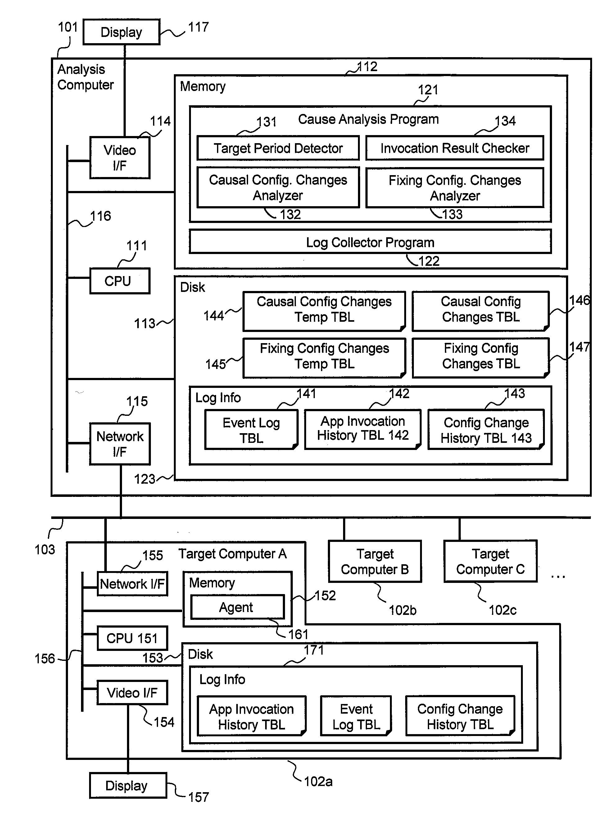
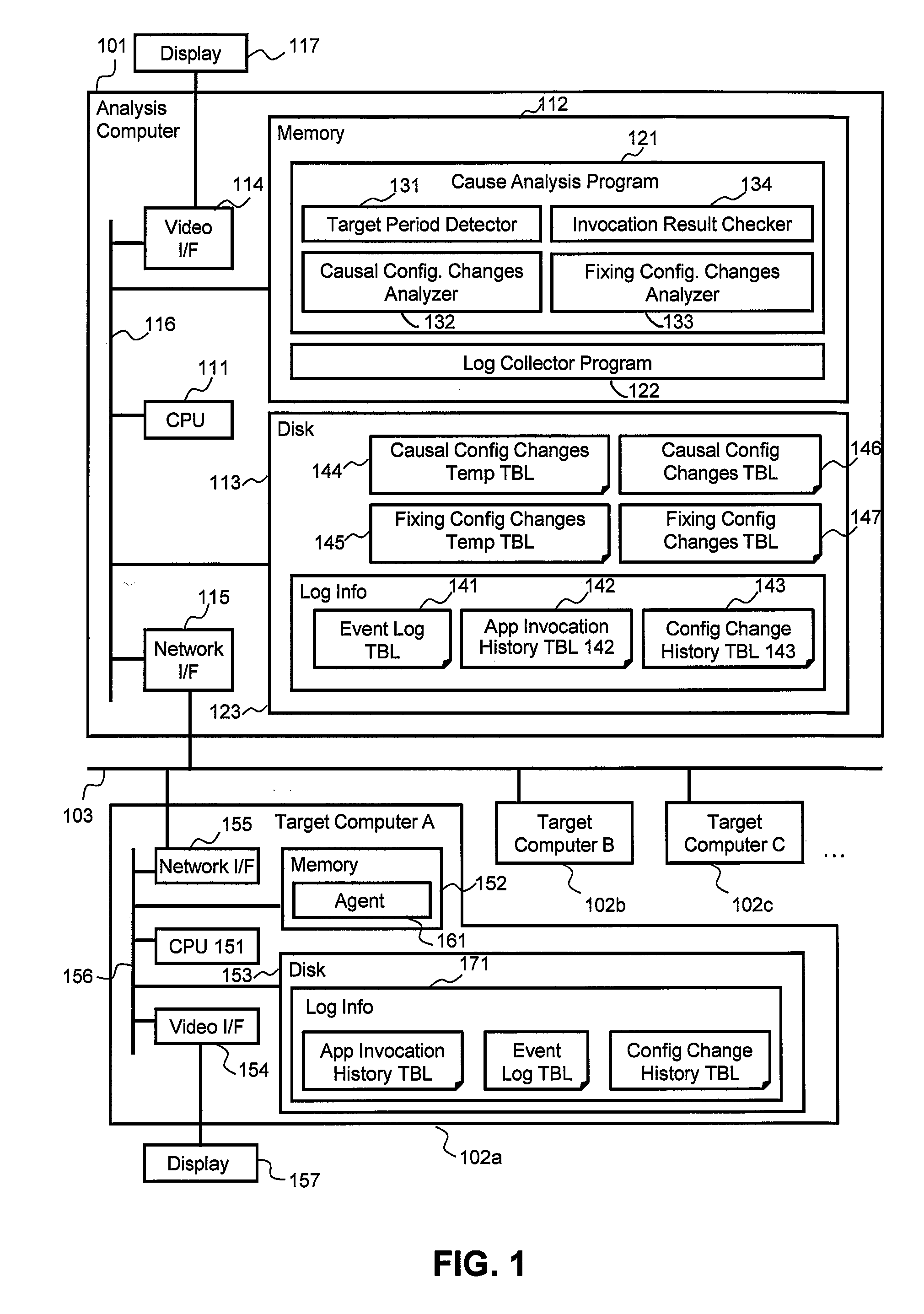
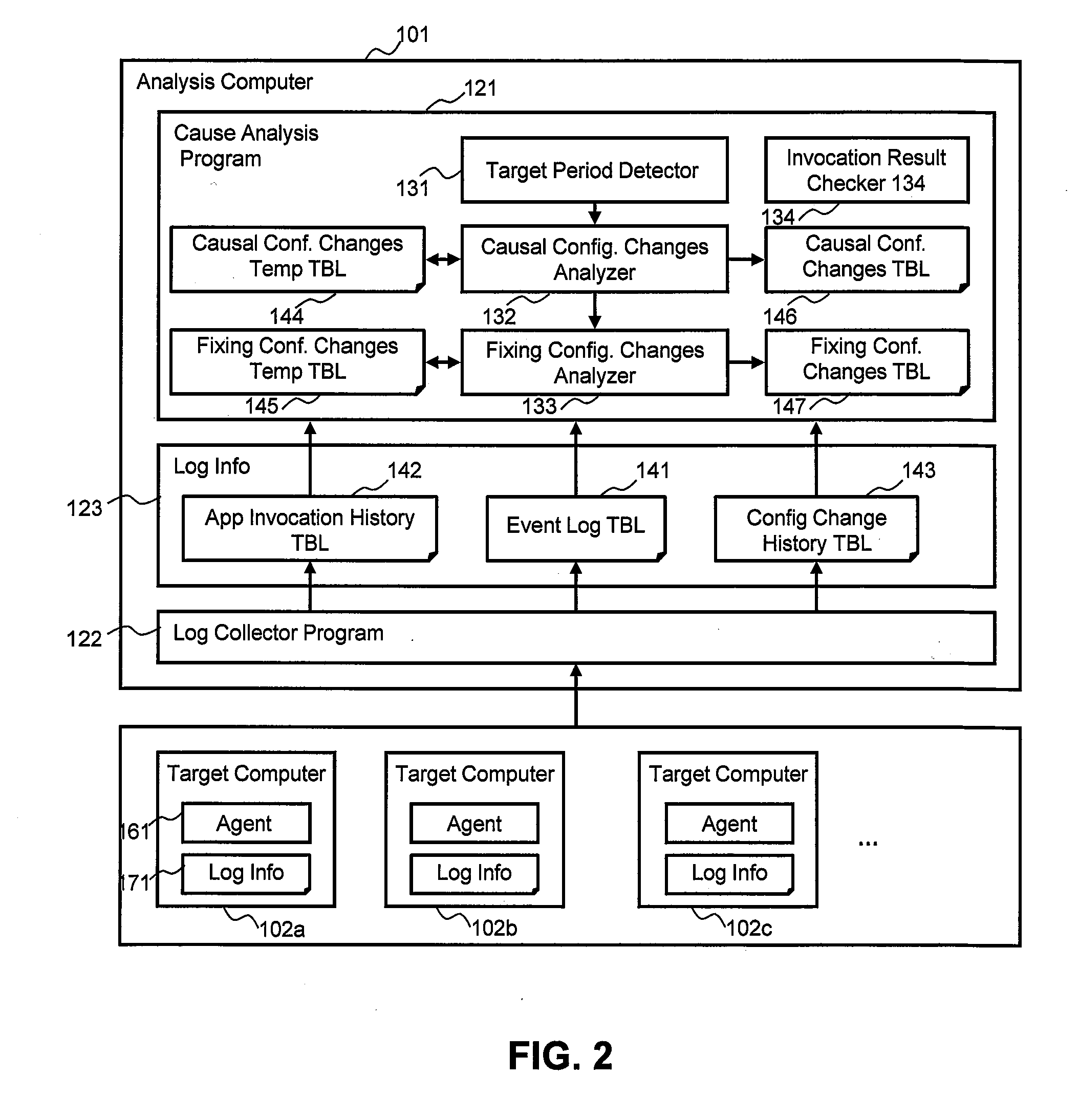
[0070]FIG. 1 illustrates an example of a hardware configuration for a client-server architecture for which the method and apparatus of the present invention is considered applicable. An analysis computer 101 and multiple target computers 102 are coupled by way of a LAN 103. The analysis computer 101 is a general-purpose computer comprising a CPU 111, a memory 112, a disk 113, a video interface 114 and a network interface 115. The respective elements are coupled via a system bus 116. The analysis computer 101 comprises a cause analysis program 121 and a log collector program 122 inside the memory 112. The cause analysis program 121 comprises a target period detector 131, a causal configuration changes analyzer 132, a fixing configuration changes analyzer 133, and an invocation result checker 134 executed by the CPU 111. The analysis computer 101 comprises a causal configuration changes temporary table 144, a fixing configuration changes tempo...

second embodiment

B. Second Embodiment

[0125]FIG. 21 shows an example of a causal configuration changes table 146-21 in accordance with a second embodiment of the present invention. In the second embodiment, in a case where the same analysis was performed in the past, the cause analysis program 121 reuses and displays the result of the analysis and storage carried out in the past. To do this, the causal configuration changes table 146 of FIG. 10 must be expanded. The columns 1001 through 1005 in FIG. 21 are the same as those in FIG. 10. In addition, new columns for an application name 2101 and an analysis date / time 2102 are introduced. For example, a record 2111 shows that an analysis of the application name “DOC EDITOR” was carried out at the analysis date / time “Jun. 5, 2008 14:20:12”. In a case where the application name is “DOC EDITOR”, and an analysis condition such that the target period detector 131 result be the same is specified, the cause analysis program 121 is able to display the analysis r...

third embodiment

C. Third Embodiment

[0127]FIG. 23 shows an example of a causal configuration changes table 146-23 in accordance with a third embodiment of the present invention. In the third embodiment, the cause analysis program 121 performs an analysis based on a combination of configuration changes. To do this, the causal configuration changes table 146 of FIG. 10 must be expanded. As shown in FIG. 23, the columns 1001 through 1005 are the same as those in FIG. 10. In addition, a new column for a combination ID 2301 is introduced. Records 2311 through 2317 exist here. For example, the record 2311 shows that an analysis was performed by using all of the combinations of the respective configuration changes. The same concept may be applied to expand the fixing configuration changes table 147 of FIG. 12.

[0128]FIG. 24 is an example of a flowchart describing a causal configuration changes analysis process executed by the causal configuration changes analyzer 132 in accordance with the third embodiment ...


PUM


Abstract

In a computer system that comprises multiple target computers and an analysis computer, one or more first target computers, in which a predetermined application has been installed and invoked, send a log comprising information of multiple configuration changes that have been made prior to invoking the predetermined application to the analysis computer, and the analysis computer receives the log and computes, for each type of configuration change and based on the log, an invocation failure rate which is a percentage at which the invocation of the predetermined application fails subsequent to the configuration change. Then, a second target computer receives, from the analysis computer, first information comprising an invocation failure rate for each type of configuration change related to the predetermined application, and based on the invocation failure rate, displays the type of configuration change that is the cause of the failure of the predetermined application invocation.

Description

TECHNICAL FIELD[0001]The present invention generally relates to a cause analysis in a computer, and more specifically, to a cause analysis accompanying a change in a configuration for finding a solution to an application failure without using a knowledge database by analyzing the configuration change.BACKGROUND ART[0002]One of the most stressful jobs for an administrator of a desktop computing environment is the cause analysis (troubleshooting) of a case in which trouble has occurred. Cause analysis is also a deciding factor for help desk personnel, who must provide a caller with a solution. An end user tends to install numerous types of software and change OS settings, and this can create problems. In addition, the configuration of a computer can be changed without the end user realizing it due to the numerous upgrade programs that routinely run on the end user's computer. Therefore, there are cases where the end user does not know when a configuration fault occurred, and cannot re...

Claims


Application Information

Patent Timeline
IPC IPC(8): G06F15/177
CPCG06F11/3476G06F11/079G06F11/076G06F11/0709
Inventor KOBAYASHI, EMIKOKUDO, YUTAKASUGAUCHI, KIMINORIMASUISHI, TETSUYAFUJITA, TAKAHIROONO, YOSHITSUGU
Owner HITACHI LTD
Why Eureka
Try Eureka