Brake device and method of controlling brake device

a technology of brake device and brake device, which is applied in the direction of braking system, rotary clutch, fluid coupling, etc., can solve the problem of large electric current consumed temporarily, and achieve the effect of suppressing an inrush current during a startup and reducing the startup load of an electric booster

Inactive Publication Date: 2011-12-29
NISSAN MOTOR CO LTD
View PDF8 Cites 19 Cited by
  • Summary
  • Abstract
  • Description
  • Claims
  • Application Information

AI Technical Summary

Benefits of technology

[0007]Therefore, according to the brake device and the method of controlling the brake device of the present invention, it is possible to reduce a startup load of an electric booster, thus suppressing an inrush current during a startup.

Problems solved by technology

Thus, there is a problem of an inrush current due to which a large electric current is temporarily consumed in order for the drive motor of the electric booster to produce a driving force exceeding the startup load during the startup.

Method used


Image

  • Brake device and method of controlling brake device
  • Brake device and method of controlling brake device
  • Brake device and method of controlling brake device

Examples


first embodiment

[0021]First of all, the construction of the brake device of the first embodiment is described.

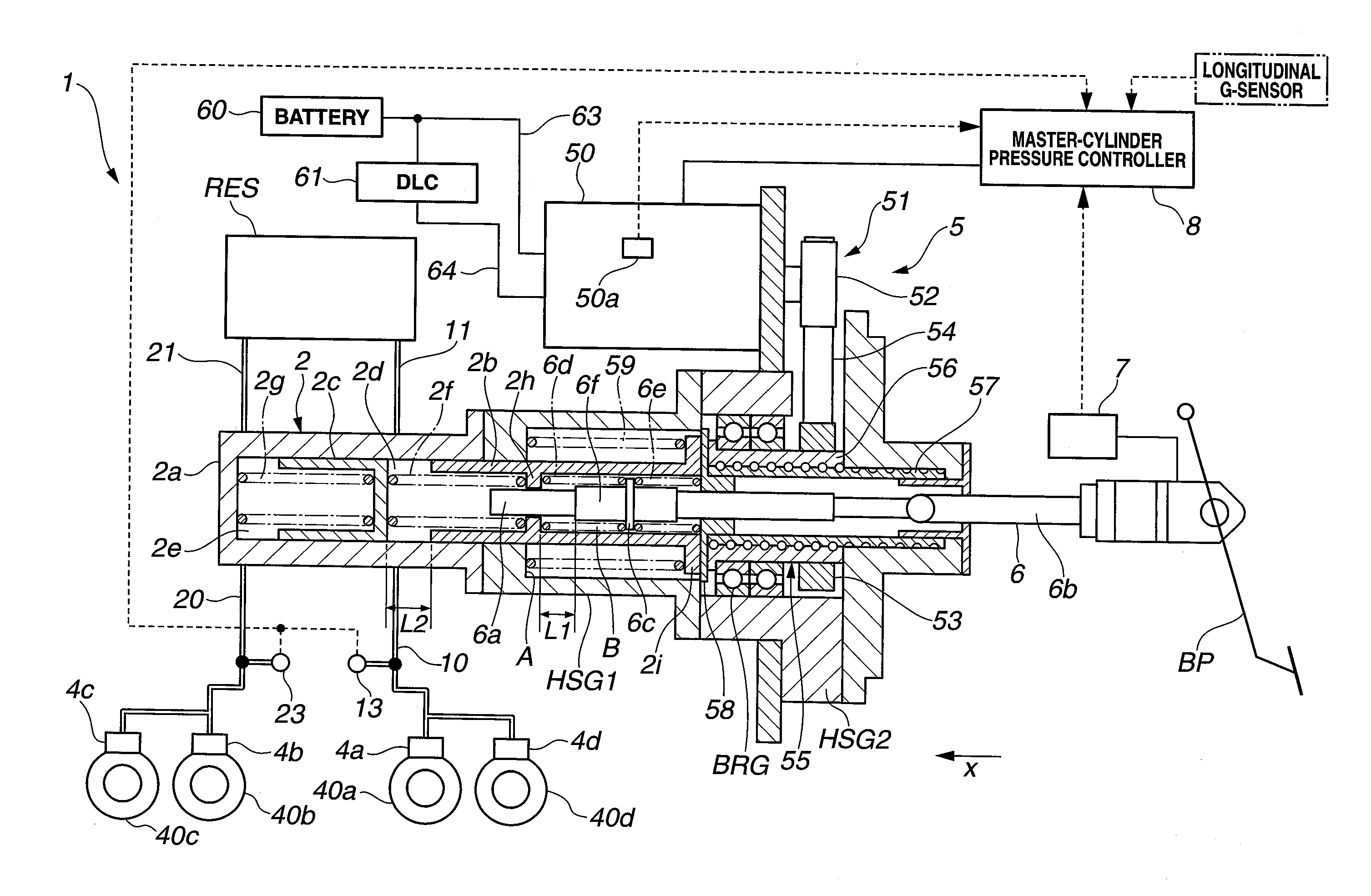
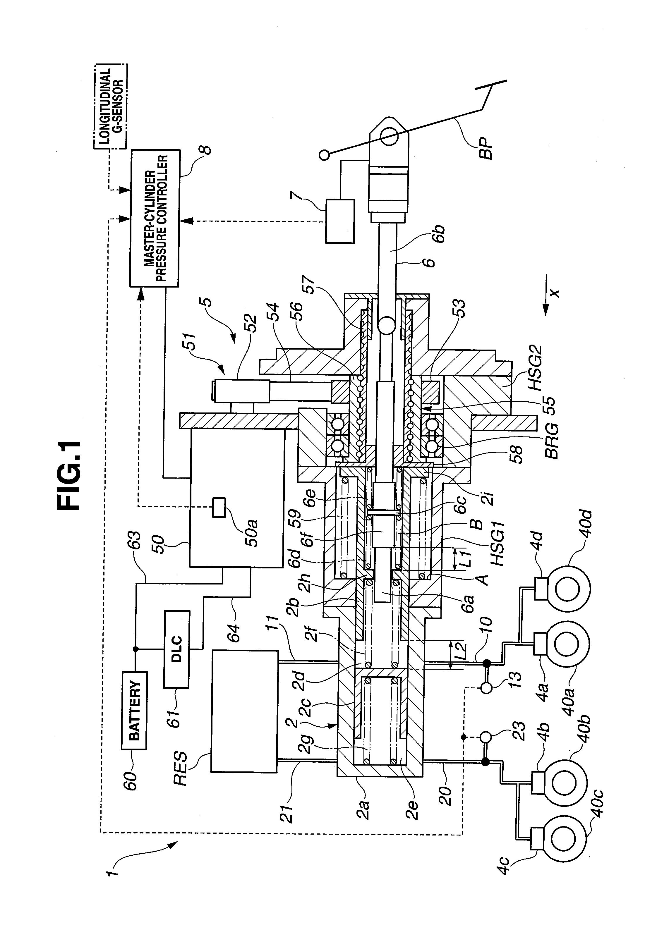
[0022]FIG. 1 is the general system diagram of the brake device 1 of the first embodiment. Brake device 1 of the first embodiment is mounted on a motor-driven electric vehicle. Brake device 1 has a dual brake system master cylinder (a dual master cylinder) 2, a reservoir tank RES, wheel cylinders 4a-4d installed on respective road wheels, an electric booster (a master-cylinder pressure control mechanism) 5 installed on the dual master cylinder 2 and an input rod 6 connected to the dual master cylinder, a brake manipulated variable detection device (an input-rod displacement detection device) 7, an electric-booster controller (a master-cylinder pressure controller) 8 configured to control the electric booster 5, a battery 60 serving as a main electric power source, an electric double layer capacitor (DLC) 61 serving as a back-up electric power source.

[0023]Input rod 6 is configured to move (a...

second embodiment

[0113]The construction of the brake device of the second embodiment is hereunder described.

[0114]FIG. 9 is the general system diagram of the brake device of the second embodiment. The fundamental construction of the brake device of the second embodiment is similar to that of the first embodiment, except that the assisting force devices (assisting force means) of the first and second embodiments differ from each other. For the purpose of comparison between the first embodiment shown in FIG. 1 and the second embodiment shown in FIG. 9, the same reference signs used to designate elements in the first embodiment will be applied to the corresponding elements used in the second embodiment. As can be appreciated from the general system diagram of FIG. 9, for the purpose of simplification of the disclosure, the first and second housing members HSG1-HSG2 of dual master cylinder 2 and the fluid-pressure sensors 13 and 23 are not shown.

[0115]Briefly speaking, in the case of the brake device of...

third embodiment

[0128]The construction of the brake device of the third embodiment is hereunder described.

[0129]FIG. 11 is the general system diagram of the brake device of the third embodiment. The fundamental construction of the brake device of the third embodiment is similar to that of the first embodiment or the second embodiment, except that the assisting force devices (assisting force means) of the first and third embodiments differ from each other and the third embodiment is somewhat modified from the second embodiment. For the purpose of comparison between the first embodiment shown in FIG. 1 and the third embodiment shown in FIG. 11, the same reference signs used to designate elements in the first embodiment will be applied to the corresponding elements used in the third embodiment. As can be appreciated from the general system diagram of FIG. 11, for the purpose of simplification of the disclosure, the first and second housing members HSG1-HSG2 of dual master cylinder 2 and the fluid-pres...


PUM


Abstract

[TASK] It is an object to provide a brake device and a method of controlling the brake device, capable of suppressing an inrush current during a startup period of an electric booster.
[MEANS TO SOLVE] In a brake device having an input rod, a piston for pressurizing a fluid pressure in a master cylinder responsively to a displacement of the input rod, and an electric booster for pushing the piston against a spring bias of a return spring of the piston and for assisting a movement of the piston in a direction for pressurizing of the fluid pressure, an input-rod displacement detection device is provided for detecting the displacement of the input rod. Also provided is an electric-booster controller configured to start up the electric booster, while applying an assisting force to the piston to push the piston against a biasing force, which forces the piston in a direction for reducing of the fluid pressure in the master cylinder, upon detecting that the input rod has been displaced a predetermined displacement at the time when a driver's brake-pedal operation starts.

Description

TECHNICAL FIELD[0001]The present invention relates to a brake device and a method of controlling the brake device.BACKGROUND ART[0002]Conventionally, there have been proposed and developed brake devices in which an electric booster is provided for magnifying a driver's brake-pedal input and for outputting the magnified input to a master cylinder. One such electric-booster equipped brake device has been disclosed in Patent document 1.[0003]Patent document 1: Japanese Patent Provisional Publication No. 2007-112426 (A)DISCLOSURE OF THE INVENTIONTask Solved by the Invention [0004]In the electric-booster equipped brake device, when a drive motor of the electric booster starts to rotate during a starting period of driver's brake-pedal operation, an inertia (startup load) is exerted on a motion converter of the electric booster due to a return-spring force acting on a primary piston. Thus, there is a problem of an inrush current due to which a large electric current is temporarily consumed...

Claims


Application Information

Patent Timeline
Patent Type & Authority Applications(United States)
IPC IPC(8): B60T13/74
CPCB60T7/042B60T8/4077B60T2270/402B60T13/745B60T8/885
Inventor ISHIZUKA, MOTOI
Owner NISSAN MOTOR CO LTD
Why Eureka
Try Eureka