Headrest Apparatus, Method of Adjusting Headrest Position, Vehicle Seat

a headrest position and headrest technology, applied in the direction of chairs, pedestrian/occupant safety arrangements, instruments, etc., can solve the problems of high cost and stability of headrest position adjustment, and achieve the effect of cost-effectiveness

Active Publication Date: 2011-12-29
NHK SPRING CO LTD
View PDF7 Cites 20 Cited by
  • Summary
  • Abstract
  • Description
  • Claims
  • Application Information

AI Technical Summary

Benefits of technology

[0014]By moving the headrest main body such that the back-set is the specific amount after contact between the head of an occupant and the headrest main body is detected, the position of the headrest can be stably adjusted to an appropriate state with a cost effective structure.
[0023]The height direction position of the headrest is accordingly also appropriately adjusted, and the restraining ability for the head of an occupant is enhanced.
[0032]Accordingly, adjusting the headrest to an inappropriate position based on a contact detected position of contact detected between the head of an occupant in an inappropriate position when the posture of the occupant has not stabilized and the headrest can be prevented by detecting contact between the head of an occupant and the headrest main body plural times, and / or by detecting strength of contact. Consequently, more stable headrest position adjustment can be achieved.
[0042]As explained above, the headrest apparatus according to the present invention employs a detection section to detect contact between the head of an occupant and a headrest front section, and moves the headrest front section so as to achieve a back-set of a specific amount between the head of an occupant and the headrest when contact has been detected between the head of an occupant and a headrest front section. An effect is accordingly exhibited of enabling the position of the headrest to be stably adjusted to an appropriate state with a cost effective configuration.

Problems solved by technology

However, in the technology described in JP-A No. 2009-154551, employing the electrostatic capacitance between the head and the headrest to adjust the position of the headrest results in a high cost, and there is sometimes issues arise with the stability of headrest position adjustment.

Method used


Image

  • Headrest Apparatus, Method of Adjusting Headrest Position, Vehicle Seat
  • Headrest Apparatus, Method of Adjusting Headrest Position, Vehicle Seat
  • Headrest Apparatus, Method of Adjusting Headrest Position, Vehicle Seat

Examples


first exemplary embodiment

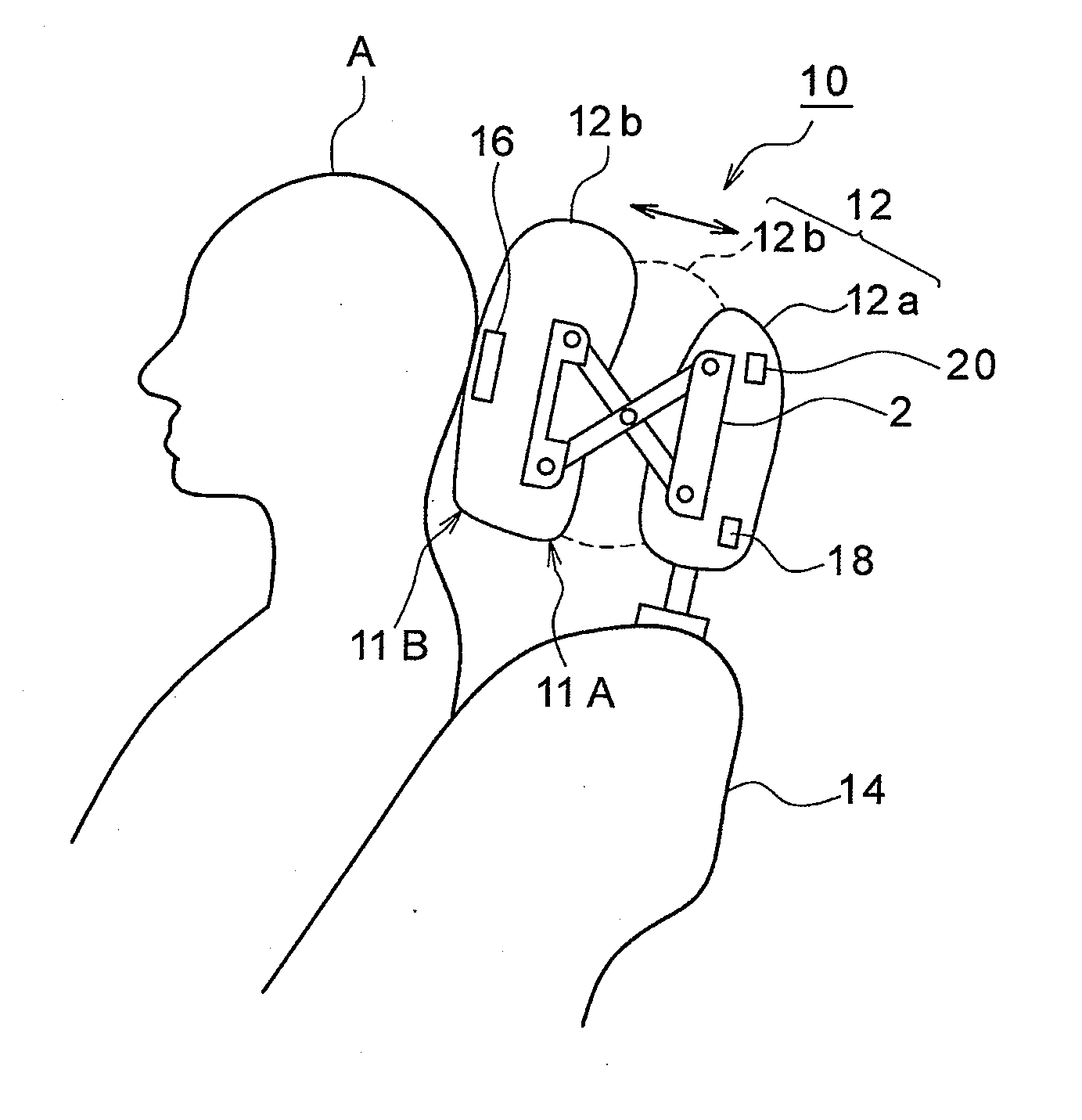
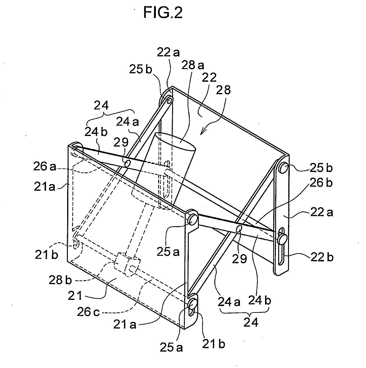
[0057]As shown in FIG. 1, a headrest apparatus 10 of the first exemplary embodiment includes: a headrest main body 12; a contact detection sensor 16 for detecting contact between the head of an occupant and the headrest; a headrest operation amount detection sensor 18 for detecting a movement amount (operation amount) of a headrest front section 12b; and a headrest control electronic control unit (ECU) 20.

[0058]The headrest main body 12 includes: a headrest rear section 12a supported at a top edge portion of a seatback 14 for resting the back of an occupant A against when seated; and the headrest front section 12b that is moveable with respect to the headrest rear section 12a within a specific range from a fully closed position 11A closest to the headrest rear section 12a to a fully open position 11B furthest away from the headrest rear section 12a. In the example of FIG. 1, the headrest front section 12b positioned at fully closed position 11A is shown with broken lines, and the he...

second exemplary embodiment

[0081]Explanation follows regarding a headrest apparatus 210 of the second exemplary embodiment. Parts of the configuration similar to that of the headrest apparatus 10 of the first exemplary embodiment are allocated the same reference numerals and further explanation thereof is omitted.

[0082]The headrest apparatus 210 of the second exemplary embodiment, as shown in FIG. 6 and FIG. 7, includes: a headrest main body 12; a contact position detection sensor 216 for detecting any contact between the head of an occupant and the headrest, and for detecting the height direction contact position; a headrest operation amount detection sensor 218; a headrest control electronic control unit (ECU) 20; and a vertical drive mechanism 252 for driving the headrest front section 12b in the height direction.

[0083]The contact position detection sensor 216 is disposed across the whole of the height direction region at the front face side of the headrest front section 12b, and outputs a detection signal...

third exemplary embodiment

[0096]Explanation follows regarding a third exemplary embodiment. The third exemplary embodiment raises stability further by detecting contact between the head of an occupant and the headrest plural times. The configuration of the headrest apparatus of the third exemplary embodiment is similar to that of the headrest apparatus of the first exemplary embodiment and so further explanation thereof is omitted.

[0097]Explanation follows regarding a headrest position control processing routine executed by a headrest apparatus of the third exemplary embodiment, with reference to FIG. 10. In the current routine, when power is supplied from a power supply, not shown in the drawings, to the headrest control ECU 20, the CPU of the headrest control ECU 20 starts executing the headrest position control processing routine program that has been read from the ROM. Explanation follows regarding a case in which the position of the headrest front section 12b when the current routine is started (initial...


PUM


Abstract

There is provided a headrest apparatus including: a headrest main body provided at a top edge portion of a seatback; a detection section to detect contact between the head of an occupant seated in the seat and the headrest main body; a moving section that moves the headrest main body in the vehicle front-rear direction; and a controller that controls the moving section such that the headrest main body is moved forward until contact between the head of an occupant and the headrest main body is detected by the detection section, and, when contact between the head of an occupant and the headrest main body has been detected by the detection section, controls the moving section to move the headrest main body such that there is a specific amount of back-set separation distance in a horizontal direction between the head of an occupant and the headrest main body.

Description

CROSS-REFERENCE TO RELATED APPLICATION[0001]This application is based on and claims priority under 35 USC 119 from Japanese Patent Application No. 2010-143753 filed on Jun. 24, 2010, the disclosure of which is incorporated by reference herein.BACKGROUND[0002]1. Technical Field[0003]The present invention relates to a headrest apparatus, a method of adjusting headrest position, and a vehicle seat, and in particular to a headrest apparatus, a method of adjusting headrest position, and a vehicle seat capable of automatically adjusting the position of a headrest to an appropriate state.[0004]2. Related Art[0005]A proposal has been made for a headrest position adjustment apparatus and a headrest position adjustment method in which the electrostatic capacitance between the head of a person seated in a seat and a headrest is measured using a detection electrode disposed spanning the entire height direction region on the front face side of the headrest, and the position of the headrest is th...

Claims


Application Information

Patent Timeline
Patent Type & Authority Applications(United States)
IPC IPC(8): A47C7/36B60N2/48B60N2/90
CPCB60N2/002B60N2/0244B60N2/4808B68G2001/005B60N2/4864B68G1/00B60N2/4829B60N2/809B60N2/829B60N2/865
Inventor YAMAGUCHI, HIROYOSHIHASEGAWA, MAKOTO
Owner NHK SPRING CO LTD
Why Eureka
Try Eureka