Eureka AIR delivers breakthrough ideas for toughest innovation challenges, trusted by R&D personnel around the world.

Incremental Coder and Method for Determining a Value of Variation of Stable Positions of the Coder

a technology of stable position variation and coder, which is applied in the field of incremental coder, can solve the problems of increasing the unit cost of a coder, not being able to correctly count the variation of stable position, and being difficult to fine-tune, etc., and achieves the effect of facilitating the standardization of a coder

Active Publication Date: 2011-12-29
THALES SA
View PDF1 Cites 4 Cited by
  • Summary
  • Abstract
  • Description
  • Claims
  • Application Information

AI Technical Summary

Benefits of technology

[0007]The invention facilitates the standardization of a coder in applications where the number of positions can vary.
[0008]For this purpose, an object of the invention is to provide a coder making it possible to count up or to count down, in a dependable way, multiple positions of a base binary coding.
[0011]A coder in accordance with the invention improves the robustness of the information that it delivers. The information will be reliable whatever the initial position on which the coder starts and whatever the position on which the coder stops. These positions may be stable positions or intermediate positions. By determining the integer part of the division it is made possible to always keep the stable position immediately lower than the stopping position. The expression lower position is understood to mean a position whose binary word has a lower value in a direction of rotation defined as positive.

Problems solved by technology

This type of coder is formed of an assemblage of mechanical parts and of optoelectronic components that it is tricky to fine tune.
When standardizing, a problem is encountered when the number of intervals of the coder varies from one application to another.
It would be possible to adjust each coder of a batch individually so as to define the values chosen from among the four binary values but this increases the unit cost of a coder.
If on the other hand, during the enabling of the coder, the latter is not at a stable position, then between this initial position and any other stable position there will be an odd number of binary edges for the two codings and a simple division by two will not make it possible to correctly count the variations of stable positions notably upon reversal of the direction of motion of the coder.

Method used


Image

  • Incremental Coder and Method for Determining a Value of Variation of Stable Positions of the Coder
  • Incremental Coder and Method for Determining a Value of Variation of Stable Positions of the Coder
  • Incremental Coder and Method for Determining a Value of Variation of Stable Positions of the Coder

Examples


Embodiment Construction

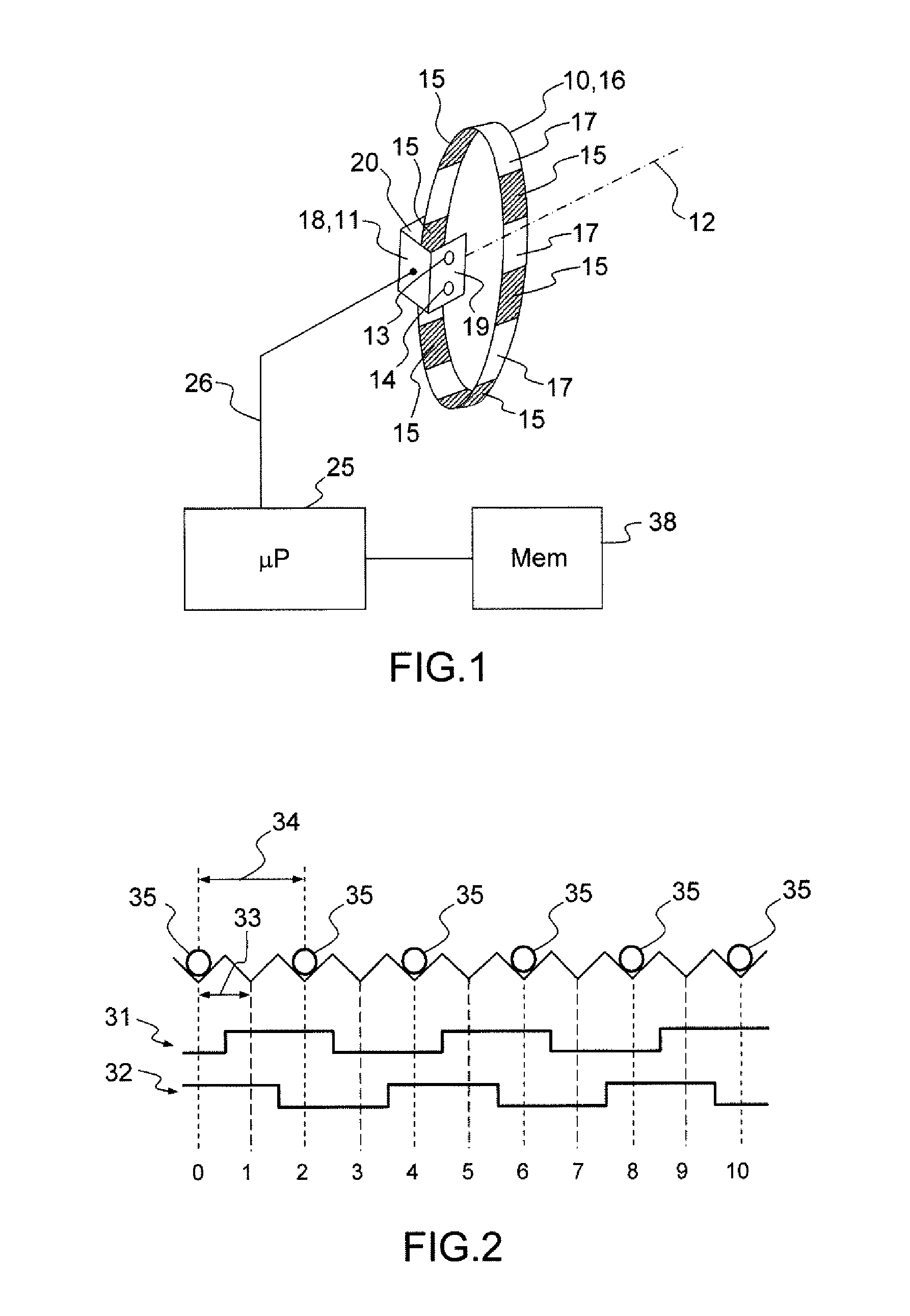
[0022]FIG. 1 represents a rotary coder comprising a movable element 10 that can move with respect to a fixed element 11. The movable element 10 is for example a button that a user can rotate about an axis 12 so as to enter an item of data into an electronic item of equipment. The fixed element 11 is secured to a housing of the coder which may be fixed in an electronic item of equipment. The coder allows for example an operator to enter data used by the item of equipment. The invention is described in relation to a rotary coder but can equally well be implemented in a linear coder.

[0023]A rotary coder is for example used in an onboard aerial navigation instrument embedded in an aircraft instrument panel. In the course of a flight, the pilot of an aircraft may have to adjust an altimeter determining the altitude thereof with respect to the pressure of the air surrounding the aircraft. In the cruising phase, the altitude is given with respect to a standard pressure of the atmosphere an...


PUM


Abstract

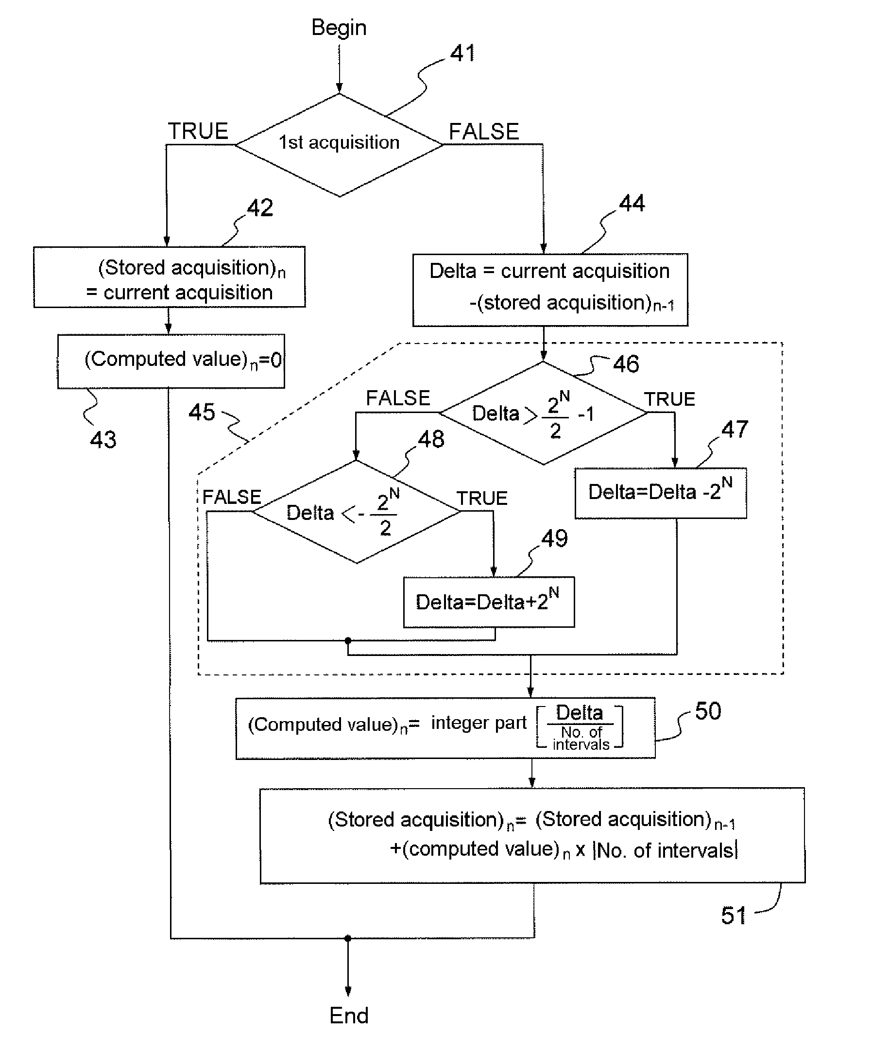
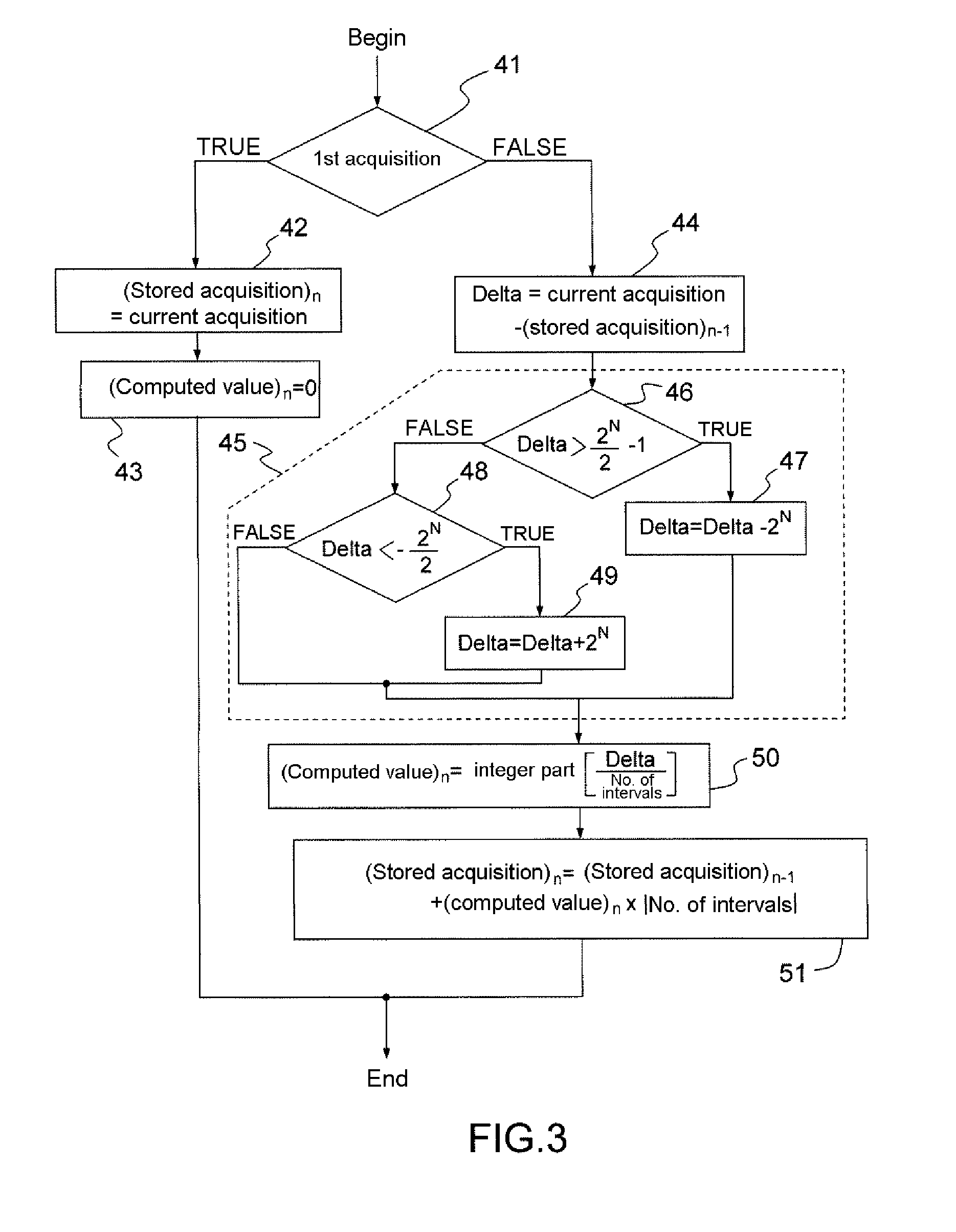
An incremental coder in which stable positions of the coder are defined by multiples of an increment of the coder. The coder computes a difference between a binary word obtained for a current stable position and a binary word obtained for a previous stable position, and computes the value of variation of stable positions by determining the integer part of the division of the difference by the number of increments between two stable positions.

Description

CROSS-REFERENCE TO RELATED APPLICATION[0001]This application claims priority to foreign French patent application No. FR 0906274, filed on Dec. 23, 2009, the disclosure of which is incorporated by reference in its entirety.BACKGROUND[0002]The invention relates to an incremental coder and to a method for determining the binary signals representing increments of relative position of two elements of the coder, the two elements being mobile with respect to one another. These coders, for example optical and angular, are used like potentiometers, for example for the manual control of electronic apparatuses which are sensitive to an input parameter that can vary continuously or almost continuously, but they are much more reliable than potentiometers. Typically, in an application in respect of aeronautical equipment, it is possible to use an optical angular coder to indicate to an automatic piloting computer an altitude or speed setpoint that the pilot chooses by actuating a control button ...

Claims


Application Information

Patent Timeline
Patent Type & Authority Applications(United States)
IPC IPC(8): H03M1/22
CPCG01D5/2451
Inventor FAZILLEAU, GREGORYGUINIER, DIDIER
Owner THALES SA
Why Eureka
Eureka Blog
Learn More