
Display apparatus driving circuit and method of driving display apparatus

Active Publication Date: 2011-12-29
PANASONIC SEMICON SOLUTIONS CO LTD
View PDF11 Cites 27 Cited by
  • Summary
  • Abstract
  • Description
  • Claims
  • Application Information

AI Technical Summary

Benefits of technology

[0013]Furthermore, since the heat generated at the source driver is merely an accumulation of the amount of heat generated in each display frame, and even in the still image with a large amount of generated heat, the source driver does not immediately generate heat unless the image is continuously displayed for a predetermined amount of time. The conventional technology has a problem that the image quality is highly likely to be degraded depending on the use of the display panel as a price for reducing the generated heat (reducing the power consumption), Accordingly, the conventional technology is not applicable for a high-quality display panel, and it is necessary to use multiple source drivers while reducing the number of output buffers for one source driver (reduce output channels), or to use a heat radiating sheet to reduce the amount of generated heat. However, these measures increase the set cost as described above.
[0045]According to the present invention, it is possible to reduce the amount of heat generated at the driving unit while suppressing the degradation in the image quality in the display apparatus allows decrease in the factor of the driving unit, that is, the set cost.Further Information About Technical Background to this Application

Problems solved by technology

However, although interlaced driving dramatically reduced the amount of generated heat, there is a problem that image quality blur is displayed in the display panel.
However, among still images, there are images with large amount of heat and images with small amount of heat, and switching to the interlaced driving with the still image with small amount of generated heat would only result in the degradation in the image quality.
Furthermore, since the heat generated at the source driver is merely an accumulation of the amount of heat generated in each display frame, and even in the still image with a large amount of generated heat, the source driver does not immediately generate heat unless the image is continuously displayed for a predetermined amount of time.
The conventional technology has a problem that the image quality is highly likely to be degraded depending on the use of the display panel as a price for reducing the generated heat (reducing the power consumption), Accordingly, the conventional technology is not applicable for a high-quality display panel, and it is necessary to use multiple source drivers while reducing the number of output buffers for one source driver (reduce output channels), or to use a heat radiating sheet to reduce the amount of generated heat.
However, these measures increase the set cost as described above.

Method used


Image

  • Display apparatus driving circuit and method of driving display apparatus
  • Display apparatus driving circuit and method of driving display apparatus
  • Display apparatus driving circuit and method of driving display apparatus

Examples


embodiment 1

Effects of Embodiment 1

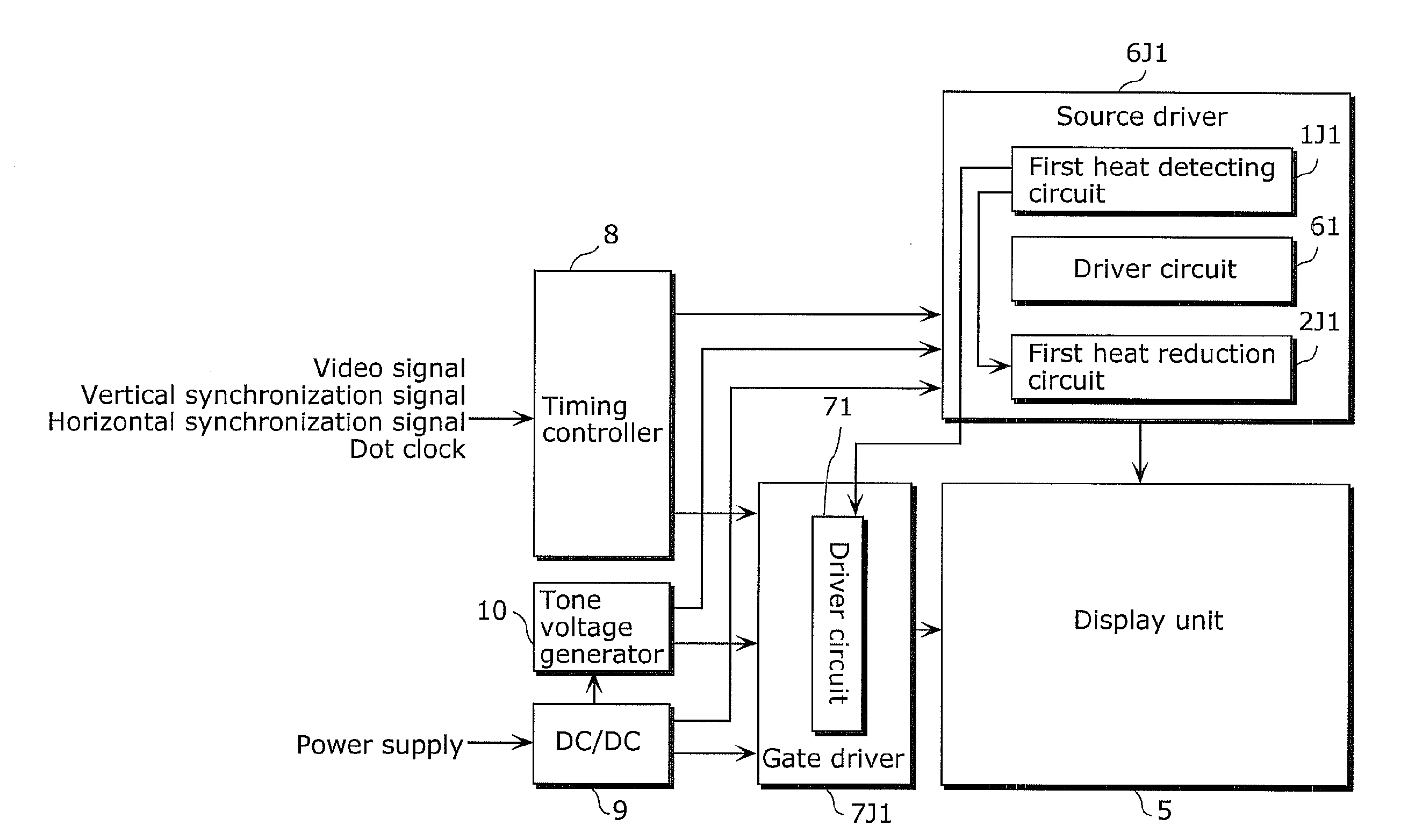
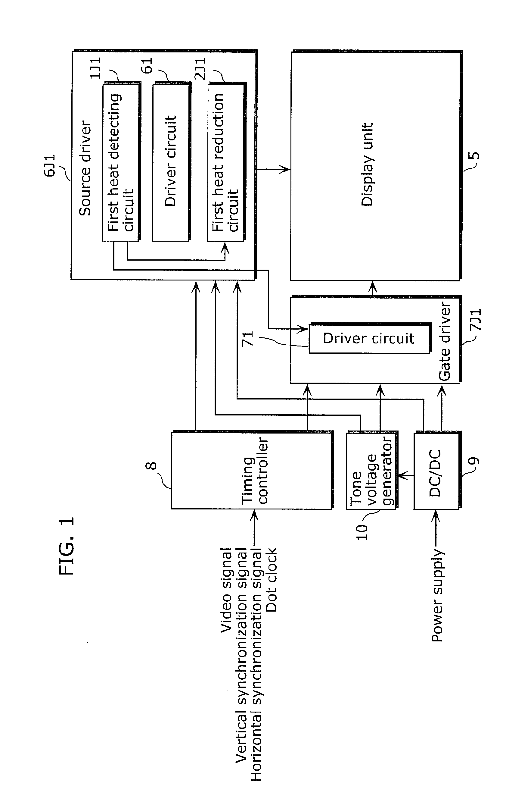
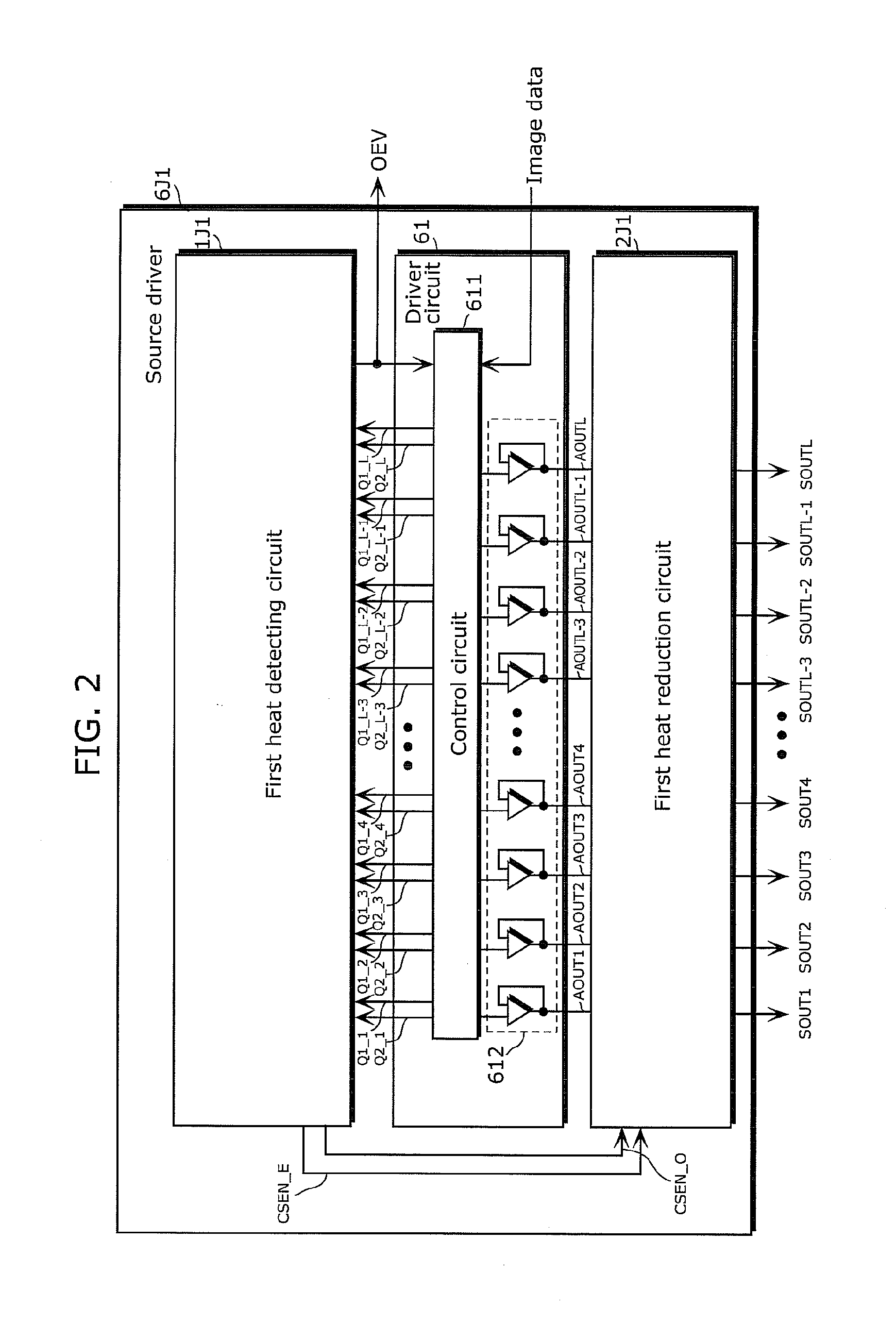
[0266]As described above, the display apparatus and the display apparatus driving circuit in Embodiment 1 includes a heat detecting circuit which detects the amount of heat generated at the source driver, and determines whether or not the detected amount of generated heat exceeds one or more set reference values. After that, the display apparatus and the display apparatus driving circuit according to Embodiment 1 changes the display driving method to reduce the amount of generated heat according to the level of the detected amount of generated heat, that is, according to the magnitude relationship between the detected amount of generated heat and the reference value.

[0267]With this, the display apparatus and the display apparatus driving circuit according to Embodiment 1 can effectively reduce the amount of heat generated at the source driver. Accordingly, instead of determining whether the image is a still image or a moving image, it is possible to detect the...

embodiment 2

Variation of Embodiment 2

[0317]As described above, Embodiment 2 is an example in which the present invention is applied to the case in which the gate driver that does not have the output enabling function (output enable signal OEV not available) or that does not use the output enabling function for some reason, by adding the second heat reduction circuit 3J2.

[0318]In the variation of Embodiment 2 as follows describes a variation of the present invention that does not require the second heat reduction circuit 3J2 even when the gate driver that does not have the output enabling function (output enable signal OEV not available) or that does not use the output enabling function for some reason.

[0319]FIG. 23 illustrates an example of block configuration of the display apparatus according to a variation of Embodiment 2. The difference from the display apparatus according to Embodiment 2 is that the source driver 6J2 is replaced with the source driver 6J23, and the gate driver 7J2 is repla...

embodiment 3

Effects of Embodiment 3

[0371]As described above, the display apparatus and the display apparatus driving circuit include n (n is a natural number) source drivers. Furthermore, at least one heat detecting circuit is incorporated in at least one of the n source drivers.

[0372]The display apparatus and the display apparatus driving circuit according to Embodiment 3 includes, in the same manner as Embodiments 1 and 2, a heat detecting circuit which detects the amount of heat generated at the source driver, and determines whether or not the detected amount of generated heat exceeds one or more set reference values. After that, the display apparatus and the display apparatus driving circuit according to Embodiment 3 changes the display driving method to reduce the amount of generated heat according to the level of the detected amount of generated heat, that is, according to the magnitude relationship between the detected amount of generated heat and the reference value.

[0373]Furthermore, t...


PUM


Abstract

A display apparatus driving circuit capable of reducing the amount of heat generated at a driving unit while suppressing degradation in image quality is provided. A display apparatus driving circuit according to the present invention includes: a source driver for driving a display unit; a heat detecting circuit for detecting amount of heat generated at the source driver, and outputting a heat detection signal when the detected amount of generated heat is equal to or larger than a predetermined reference value; and a heat reduction circuit for changing, when the heat detection signal is received, a driving method of the display unit to reduce the amount of heat generated at said source driver.

Description

CROSS REFERENCE TO RELATED APPLICATION[0001]This is a continuation application of PCT application No. PCT / JP2010 / 006589 filed on Nov. 10, 2010, designating the United States of America.BACKGROUND OF THE INVENTION[0002](1) Field of the Invention[0003]The present invention relates to display apparatus driving circuits and methods of driving display apparatuses, and particularly relates to a display apparatus driving circuit and a method of driving the display apparatus which reduce the amount of heat generated at a driving unit which drives a display panel.[0004](2) Description of the Related Art[0005]A display apparatus including a display panel includes a driving unit for driving the display panel (for example, see Patent Literature 1: Japanese Patent No. 3233895). FIG. 49 illustrates the configuration of a conventional display apparatus according to Patent Literature 1. Here, the driving unit in the conventional display apparatus shall be described with reference to FIG. 49.[0006]A...

Claims


Application Information

Patent Timeline
IPC IPC(8): G09G5/00
CPCG09G3/3688G09G2310/0202G09G2330/045G09G2310/0291G09G2330/023G09G2310/0224
Inventor OTANI, YOSHIYUKIKOJIMA, HIROSHINISHIHARA, MASAAKIISHIKAWA, TOMOYASUYAMA, TOORU
Owner PANASONIC SEMICON SOLUTIONS CO LTD
Learn More