Ball bearing retainer

Inactive Publication Date: 2016-06-23
NTN CORP
View PDF0 Cites 3 Cited by
  • Summary
  • Abstract
  • Description
  • Claims
  • Application Information

AI Technical Summary

Benefits of technology

The patent describes a new design for a ball bearing retainer that allows for high-speed operation. The retainer is designed with outer diameter restriction, which prevents it from interfering with the balls even when there is a centrifugal force during operation. The guide surfaces of the retainer are flat and inclined, which allows lubricant to easily reach and remove heat generated. The retainer is not tightly fitted onto the ball, reducing local heat generation. The retainer can be easily demolded using a sliding mold method. The retainer is guided by each ball in point or line contact, reducing heat generated. The patent also describes different versions of the ball bearing retainer that allow for different levels of heat reduction and high load capacity.

Problems solved by technology

This is because, when an inner diameter restriction type ball guide retainer is rotated at a high speed, the retainer expands due to action of a centrifugal force or the retainer whirls, and thus resistance applied to a ball receiving portion (an inner diameter side portion in the case of an inner diameter restriction type) of the retainer or an amount of heat generated at the ball receiving portion, due to contact between the ball receiving portion and balls, increases gradually, thereby impairing normal rotation.
This is because, when an inner diameter restriction type ball guide retainer is rotated at a high speed, the retainer expands due to action of a centrifugal force or the retainer whirls, and thus resistance or an amount of heat generated due to contact between a ball receiving portion of the retainer and balls increases gradually, thereby impairing normal rotation.
When the normal rotation is impaired, local heat generation and insufficient lubrication occur at the contact surface, leading to an abnormal increase in the temperature of the bearing.
However, in the conventional retainer, since each of the claw portions is located at the center of the axial width of the pocket and greatly projects, flow of a lubricant in the pocket is not quite sufficient.
Normally, these surfaces are subjected to grind finishing, which causes an increase in cost.

Method used


Image

  • Ball bearing retainer
  • Ball bearing retainer
  • Ball bearing retainer

Examples


Embodiment Construction

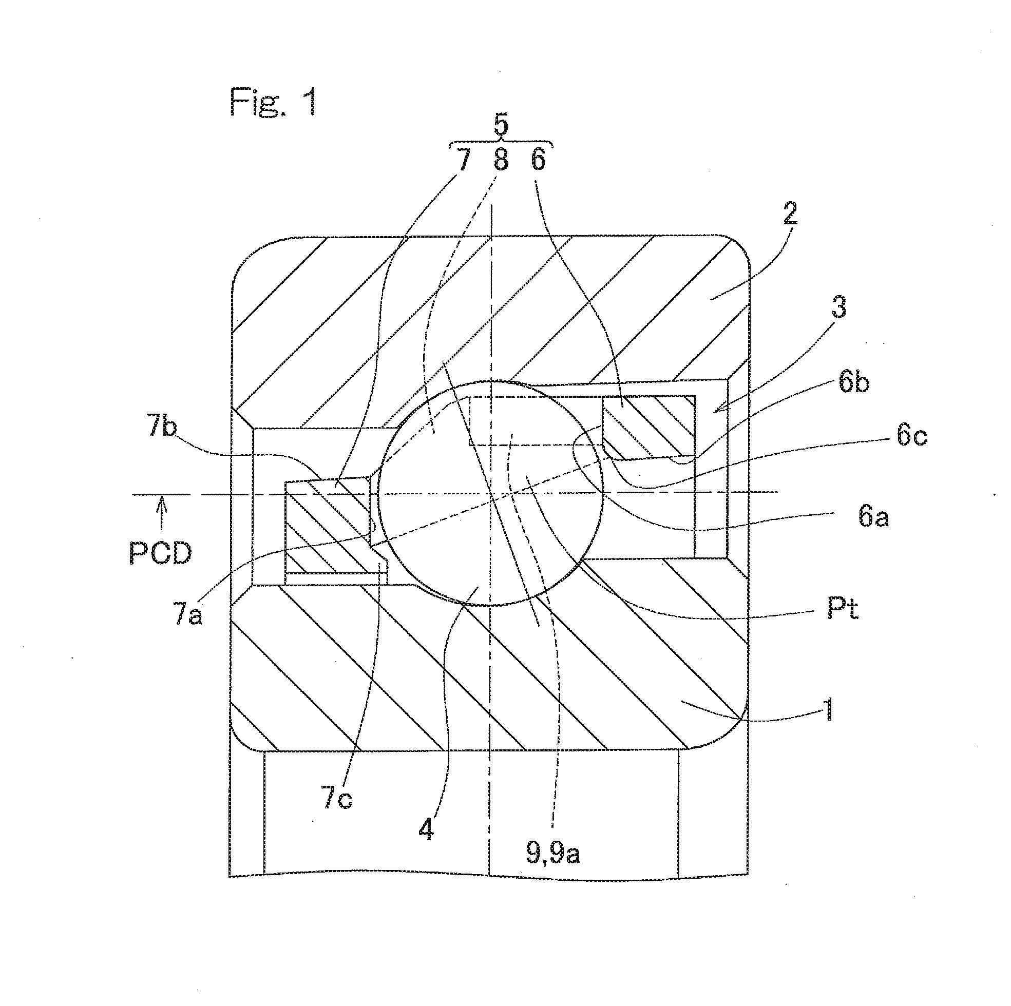
[0057]A first embodiment of the present invention will be described with reference to FIGS. 1 to 6. A ball bearing retainer according to this embodiment is applied particularly to a retainer of an angular contact ball bearing for a main shaft of a machine tool. FIG. 1 is a longitudinal cross-sectional view of an angular contact ball bearing in which the ball bearing retainer is used. In the angular contact ball bearing, balls 4 are retained by a retainer 3 and interposed between an inner ring 1 and an outer ring 2. The balls 4 are formed of, for example, steel balls, ceramics, or the like.

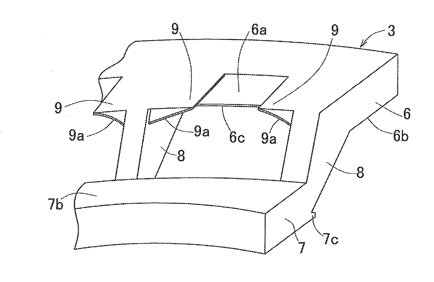
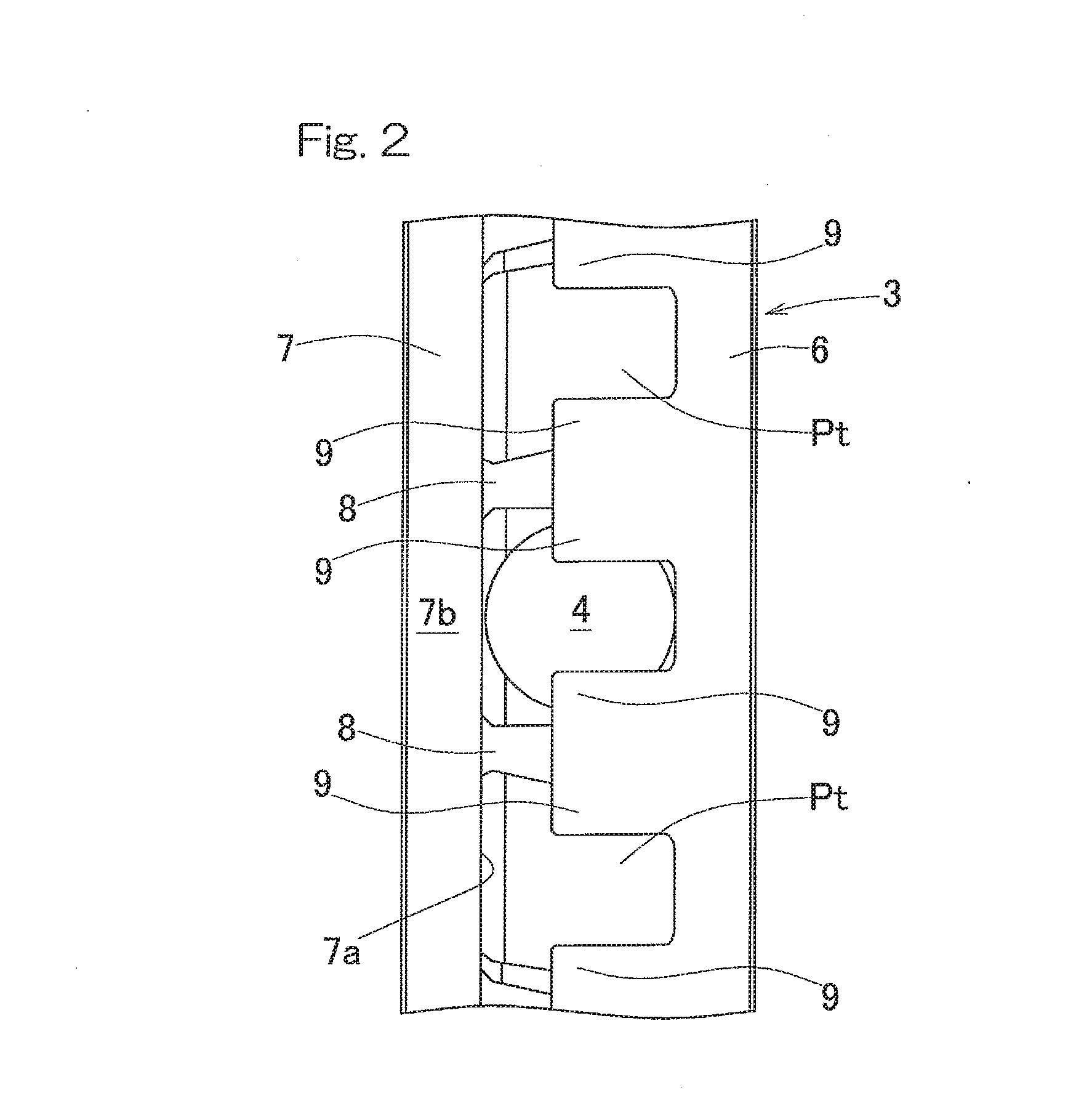
[0058]The retainer 3 is an outer diameter restriction type ball guide retainer. The retainer 3 retains the balls 4, which are interposed between the inner ring 1 and the outer ring 2, in pockets Pt which are provided in a circular ring portion 5 and at a plurality of positions in a circumferential direction. The circular ring portion 5 includes: annular portions 6 and 7 disposed at both sides in an...


PUM


Abstract

A ball guide type ball bearing retainer (3) according to the present invention retains balls (4) in pockets (Pt) provided in a circular ring portion (5), and the circular ring portion (5) includes annular portions (6, 7) disposed at both sides in an axial direction and pillar portions (8) which connect the annular portions (6, 7). Each pocket (Pt) is formed by the annular portions (6, 7) at the both sides and the pillar portions (8) adjacent to each other. At outer diameter portions of the pillar portions (8), outer diameter restriction portions (9) are provided which extend toward a pocket side and restrict and guide the balls (4) from an outer diameter side with guide surfaces (9a) thereof, and are inclined flat surfaces which are inclined so as reach a large diameter side as extending from the pillar portions (8) toward a pocket (Pt) center side.

Description

CROSS REFERENCE TO THE RELATED APPLICATION[0001]This application is a continuation application, under 35 U.S.C. §111(a), of international application No. PCT / JP2014 / 071750, filed Aug. 20, 2014, which claims priority to Japanese patent application No. 2013-179581, filed Aug. 30, 2013, the entire disclosure of which is herein incorporated by reference as a part of this application.BACKGROUND OF THE INVENTION[0002]1. Field of the Invention[0003]The present invention relates to a retainer for a ball bearing that is used for, for example, a main shaft of a machine tool or the like.[0004]2. Description of Related Art[0005]A ball bearing retainer rotates while being guided by a bearing component other than the retainer, that is, an inner ring, an outer ring, or balls. Ball bearing retainers are classified into three types, “inner ring guide retainer”, “outer ring guide retainer”, and “ball guide retainer”, on the basis of a component that guides the retainer. In general, an inner diameter ...

Claims


Application Information

Patent Timeline
IPC IPC(8): F16C33/38F16C19/16
CPCF16C33/3887F16C19/166F16C33/3856F16C19/163F16C33/6681
Inventor KOYAMA, MINEOINOUE, WAKANAKOSUGI, FUTOSHI
Owner NTN CORP
Why Eureka
Try Eureka