Fiber optic module release mechanism

Inactive Publication Date: 2008-03-25
FOURTE INT SDN BHD
View PDF3 Cites 18 Cited by
  • Summary
  • Abstract
  • Description
  • Claims
  • Application Information

AI Technical Summary

Benefits of technology

[0016]An advantage of the present invention is that the two piece release mechanism provides a means to smoothly remove the transceiver module from the cage.
[0017]Another advantage of the present invention is that the locking mechanism provides seating of the transceiver module.
[0018]Still another advantage of the present invention is that it provides a safeguard against premature removal of the transceiver module.

Problems solved by technology

These systems require ever increasing data transfer rates to perform the highly complex tasks that drive the systems, such as digital signal processing, image analysis, and communications.
As the density of the optical arrays increases, coupling a fiber optic cable to the arrays becomes an increasingly complex task.

Method used


Image

  • Fiber optic module release mechanism
  • Fiber optic module release mechanism
  • Fiber optic module release mechanism

Examples


Embodiment Construction

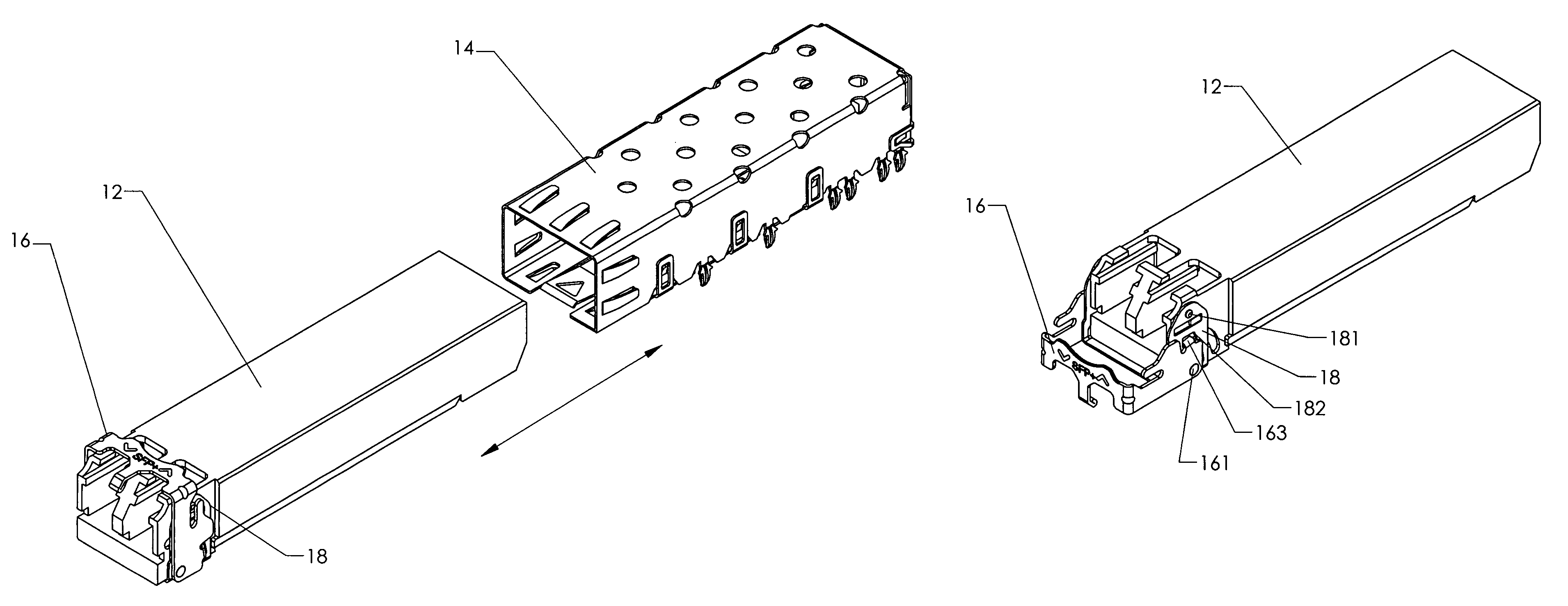
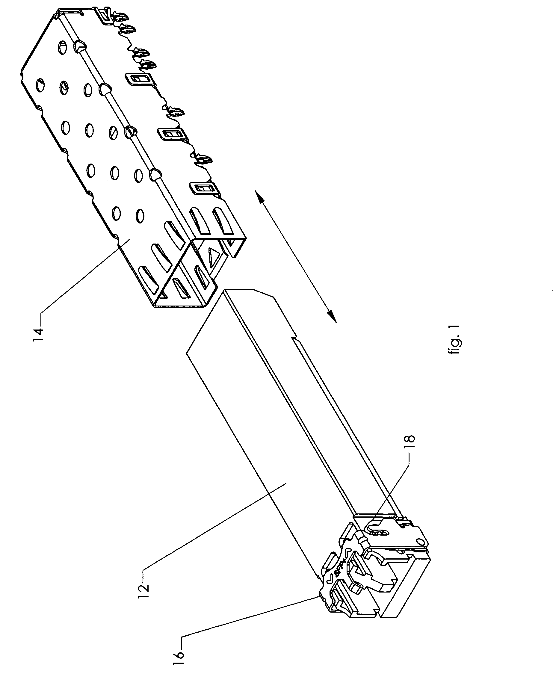
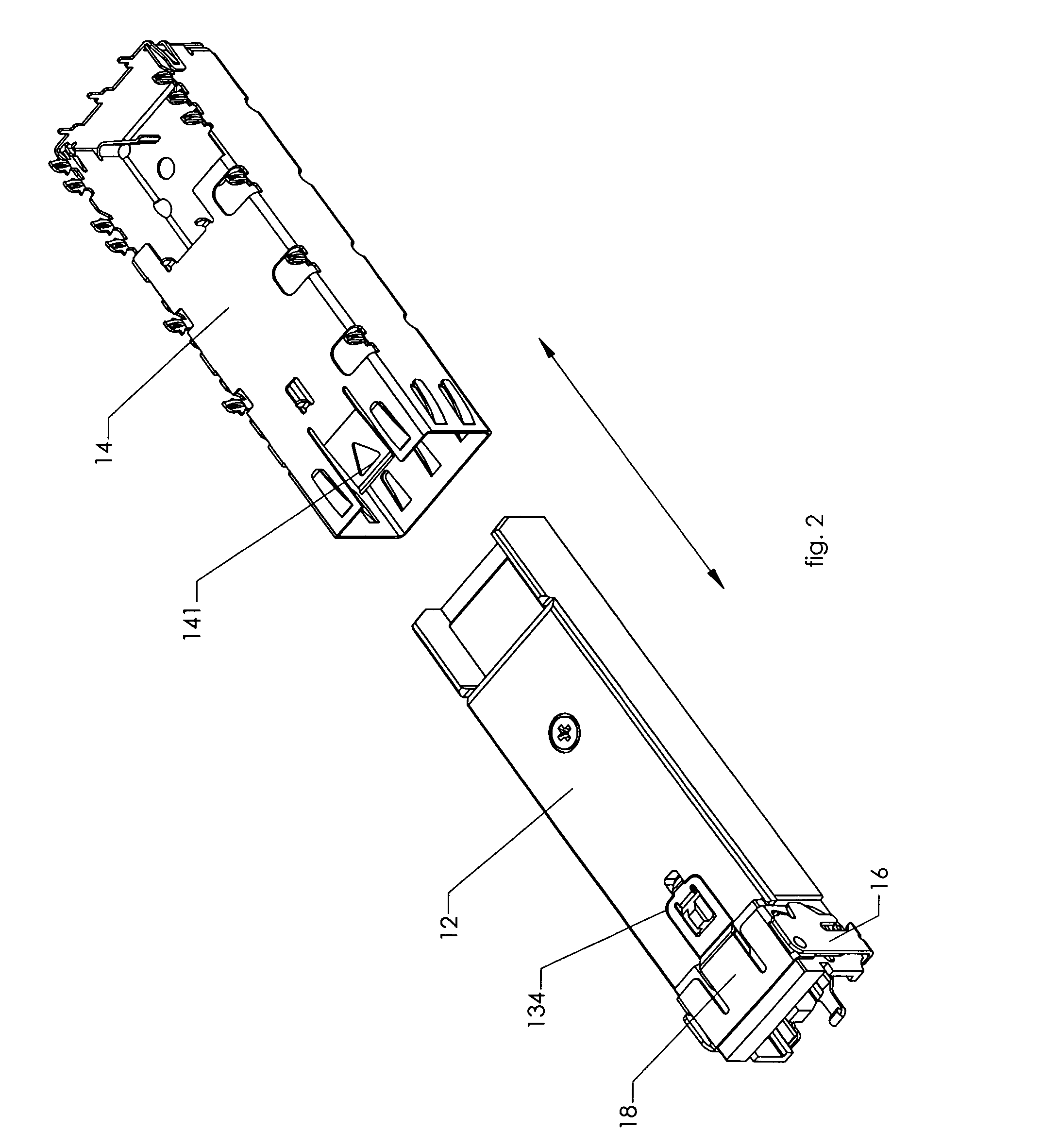
[0031]The present invention is a fiber optic module release mechanism. The release mechanism is used on a transceiver module 12 housed in a cage assembly 14 that is permanently mounted on a printed circuit board (not shown).

[0032]The release mechanism comprises a pivoting bail 16 that works in conjunction with a slide plate 18. These elements are shown in detail in FIGS. 5-9. The bail 16 is mounted on pivot axes 161 that are received in pivot mounting sockets 124 on the module 12. The bail 16 further comprises a slot 162 that receives a boss 181 protruding from the slide plate 18 to form a catch means that retains the bail 16 in the locked position.

[0033]The bail 16 further includes a tab 163 that extends through an opening 182 in the slide plate 18 and into a travel arc 121 in the module 12. The tab 163 contacts the sides of the opening 182 to cause the slide plate 18 to move when the bail 16 is rotated. The travel path of the tab 163 is defined by the travel arc 121 (90° in the pr...


PUM


Abstract

A fiber optic connector release mechanism that is used to release a transceiver module from a cage assembly includes a pivoting bail that operates a slide plate on the transceiver module. The locking mechanism comprises a locking projection on an underside of the module housing which mates with an aperture in a flexible locking tab on an underside of the cage. When the release mechanism is actuated, a flexible lifting tab on the slide plate is urged upward by a trailing edge of the locking projection on an underside of the module housing, which in turn moves the locking tab on the cage upward, thereby disengaging the locking tab from the locking projection.

Description

BACKGROUND OF THE INVENTION[0001]1. Field of the Invention[0002]The present invention relates generally to electronic module and connector devices, and more particularly is a fiber optic module release mechanism.[0003]2. Description of the Prior Art[0004]Computers and related peripheral equipment, as well as satellite and communication systems, have in the recent past evolved extremely rapidly. These systems require ever increasing data transfer rates to perform the highly complex tasks that drive the systems, such as digital signal processing, image analysis, and communications. With current demands, optical couplers are used to transfer signals over short and long distances between computers, between two circuit boards in one computer, and even between multiple chips on a single printed circuit board. The use of high speed optical signals in place of electrical interconnections increases the achievable data transfer rate.[0005]An optical transmitter / receiver module typically inclu...

Claims


Application Information

Patent Timeline
IPC IPC(8): H01R13/627
CPCG02B6/4201H01R13/6275G02B6/4261
Inventor BIANCHINI, GIONIFAJARDO, IGGONI SUNGA
Owner FOURTE INT SDN BHD
Why Eureka
Try Eureka