Time Shifted PN Codes for CW LIDAR, RADAR, and SONAR

a technology of time-shifted pn codes and lidar, which is applied in the field of range detection and absorption, can solve problems such as various drawbacks of known systems

Inactive Publication Date: 2011-12-29
NASA
View PDF5 Cites 77 Cited by
  • Summary
  • Abstract
  • Description
  • Claims
  • Application Information

AI Technical Summary

Problems solved by technology

However, known systems suffer from various drawbacks.

Method used


Image

  • Time Shifted PN Codes for CW LIDAR, RADAR, and SONAR
  • Time Shifted PN Codes for CW LIDAR, RADAR, and SONAR
  • Time Shifted PN Codes for CW LIDAR, RADAR, and SONAR

Examples


Embodiment Construction

[0031]For purposes of description herein, terms such as “upper,”“lower,”“right,”“left,”“rear,”“front.”“vertical,”“horizontal,” and derivatives may be utilized. However, it is to be understood that the invention may assume various alternative orientations and step sequences, except where expressly specified to the contrary. It is also to be understood that the specific devices and processes illustrated in the attached drawings and described in the following specification are simply exemplary embodiments of the inventive concepts defined in the appended claims. Hence, specific dimensions and other physical characteristics relating to the embodiments disclosed herein are not to be considered as limiting, unless the claims expressly state otherwise.

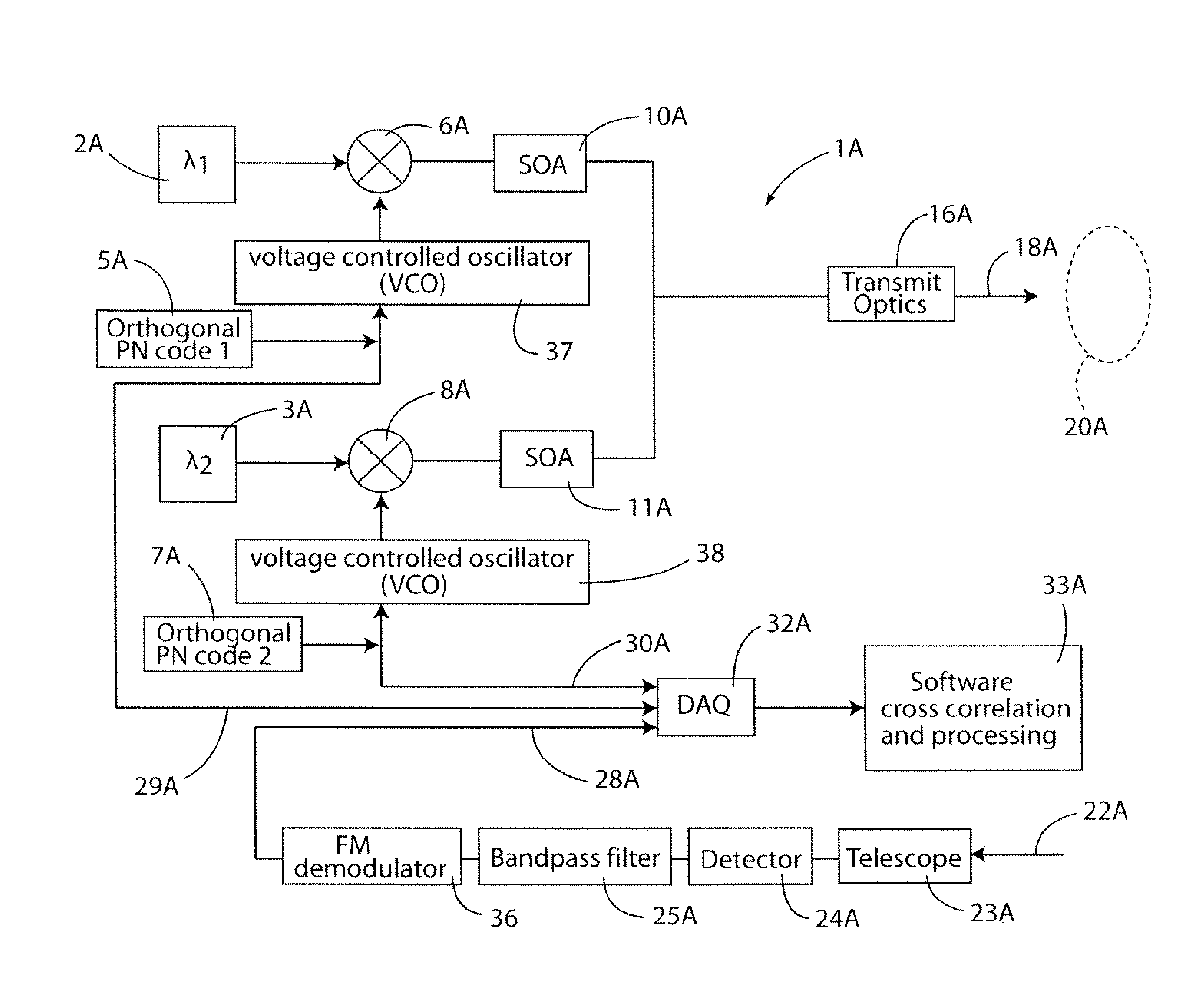
[0032]In atmospheric science it is useful to use PN codes at multiple laser wavelengths in order to measure absorption at specific ranges in order to, for example, discriminate the return of a cloud from the ground.

[0033]The present invention...


PUM


Abstract

A continuous wave Light Detection and Ranging (CW LiDAR) system utilizes two or more laser frequencies and time or range shifted pseudorandom noise (PN) codes to discriminate between the laser frequencies. The performance of these codes can be improved by subtracting out the bias before processing. The CW LiDAR system may be mounted to an artificial satellite orbiting the earth, and the relative strength of the return signal for each frequency can be utilized to determine the concentration of selected gases or other substances in the atmosphere.

Description

CROSS-REFERENCE TO RELATED PATENT APPLICATIONS[0001]This application claims the benefit of priority to U.S. Provisional Patent Application Ser. No. 61 / 357,687, filed on Jun. 23, 2010. The contents of the foregoing application are hereby incorporated by reference in their entirety.STATEMENT REGARDING FEDERALLY SPONSORED RESEARCH OR DEVELOPMENT[0002]The invention was made by employees of the United States Government and may be manufactured and used by or for the Government of the United States of America for governmental purposes without the payment of any royalties thereon or therefore.FIELD OF THE INVENTION[0003]The present invention relates generally to range detection and absorption utilizing Light Detection And Ranging (LiDAR), radar, sonar, or other signal.BACKGROUND OF THE INVENTION[0004]Various types of LiDAR, radar, and sonar have been developed to measure range. In addition to measuring distance, LiDAR has been utilized to measure the concentration of gases or other substanc...

Claims


Application Information

Patent Timeline
Patent Type & Authority Applications(United States)
IPC IPC(8): G01C3/08
CPCG01S17/325G01S17/34
Inventor CAMPBELL, JOEL F.PRASAD, NARASIMHA S.HARRISON, FENTON W.FLOOD, MICHAEL A.
Owner NASA
Why Eureka
Try Eureka