Displacement detecting device

a technology of displacement information and detection device, which is applied in the direction of optical measurement, optical radiation measurement, instruments, etc., can solve the problems of measurement error, displacement information such as displacement, shape and the like of the surface to be measured, and cannot always be accurately obtained, so as to reduce the heat generated during use and ease the effect of service conditions

Active Publication Date: 2011-12-29
DMG MORI CO LTD
View PDF7 Cites 14 Cited by
  • Summary
  • Abstract
  • Description
  • Claims
  • Application Information

AI Technical Summary

Benefits of technology

[0012]However, in the displacement detecting device disclosed in Japanese Unexamined Patent Application Publication No. H05-89480, high resolution is achieved by reducing the beam diameter of the light imaged on surface-to-be-measured. Thus, the reflected light from the surface-to-be-measured is susceptible to the influence of the surface roughness, so that the light imaged on surface-to-be-measured is scattered to therefore cause measurement error.
[0019]In view of the aforesaid problems, it is an object of the present invention to provide a displacement detecting device having wider service conditions and capable of accurately detecting position in the height direction.
[0026]Further, with the displacement detecting device according to the present invention, the absolute position information is outputted based on the reflected light from the surface-to-be-measured. Thus, the reference point and reference position of the aforesaid scale formed by the interference light can be determined based on the absolute position information, so that the displacement of the surface-to-be-measured can be correctly detected.
[0029]Since the conventional drive mechanism is not necessary, the heat generated during use can be reduced. Further, since the drive mechanism is not necessary, there will be no problem of response frequency, and therefore service conditions can be eased.

Problems solved by technology

Thus, the reflected light from the surface-to-be-measured is susceptible to the influence of the surface roughness, so that the light imaged on surface-to-be-measured is scattered to therefore cause measurement error.
Further, since high resolution is achieved by reducing the beam diameter, there are cases where fine foreign matter and / or the like attached on the surface-to-be-measured is detected, so that displacement information such as the displacement, shape and the like of the surface-to-be-measured can not always be accurately obtained.
However, in previous displacement detecting devices such as the displacement detecting device disclosed in Japanese Unexamined Patent Application Publication No.

Method used


Image

  • Displacement detecting device
  • Displacement detecting device
  • Displacement detecting device

Examples


first embodiment

1. First Embodiment

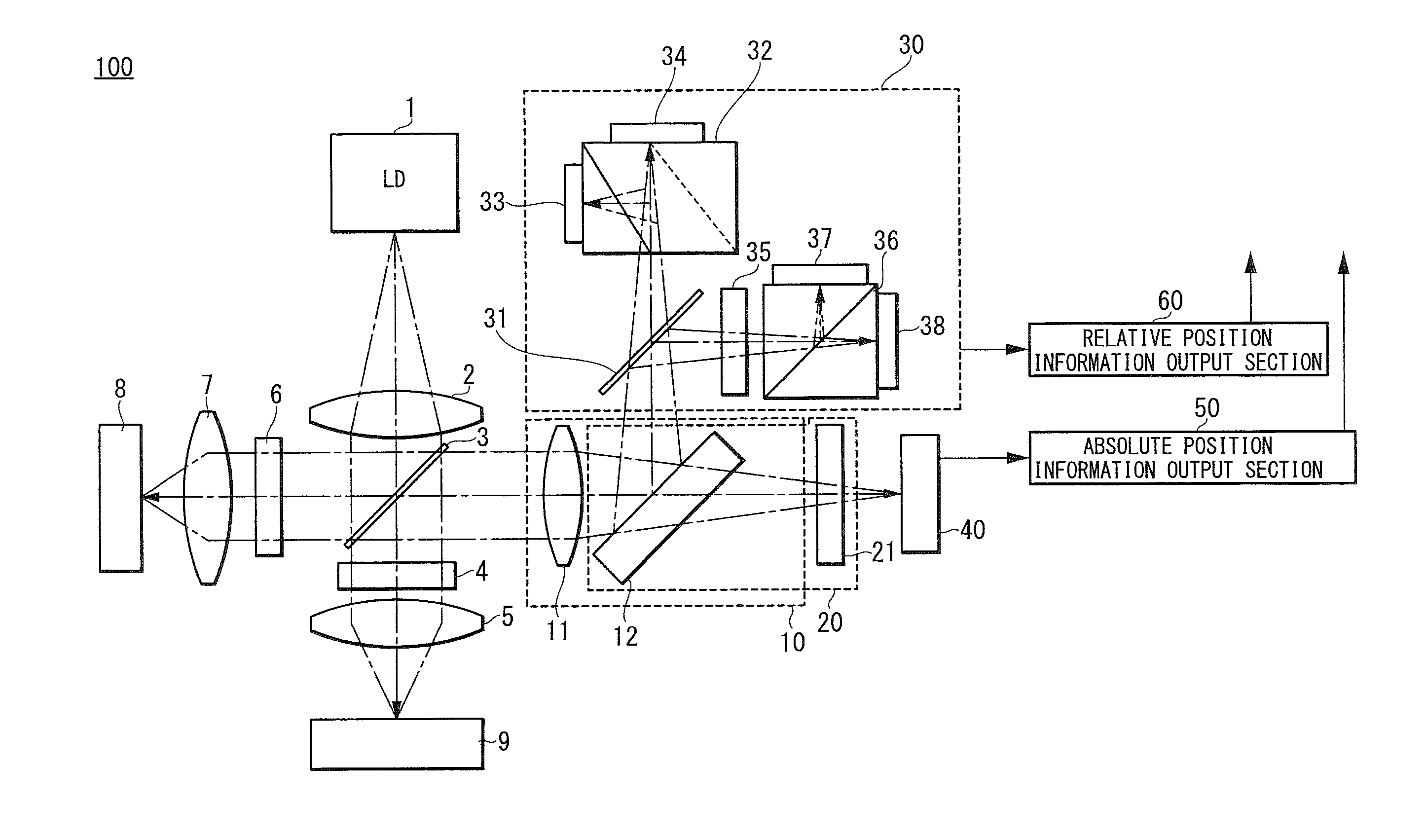
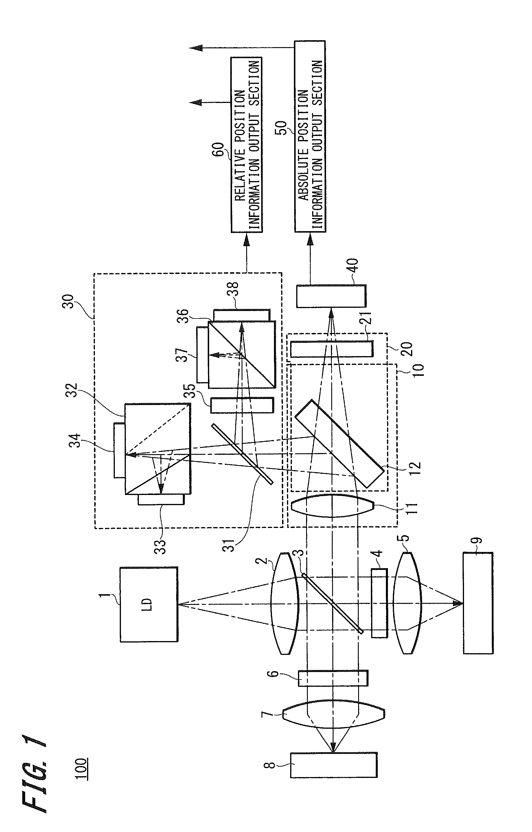
[0044]FIG. 1 is a view schematically showing the configuration of a displacement detecting device 100 according to a first embodiment of the present invention. The displacement detecting device 100 according to the present embodiment includes a light source 1, a first beam splitter 3 adapted to split the light emitted from the light source 1 into a first beam and a second beam, and a reflecting member 8 adapted to reflect the first beam split by the first beam splitter 3.

[0045]The displacement detecting device 100 further includes an objective lens 5 adapted to condense the second beam split by the first beam splitter 3 on a surface-to-be-measured of an object-to-be-measured 9, and a first light receiving section 30 adapted to receive interference light of the first beam reflected by the reflecting member 8 and the second beam reflected by the surface-to-be-measured of the object-to-be-measured 9.

[0046]The displacement detecting device 100 further includes a relat...

second embodiment

2. Second Embodiment

[0140]In the first embodiment, one light source is used. In a second embodiment to be described below, two light sources having different wavelengths are used.

[0141]FIG. 5 is a view schematically showing the configuration of a displacement detecting device 200 according to the second embodiment of the present invention.

[0142]The displacement detecting device 200 according to the present embodiment includes a first light source 101a and a first beam splitter 103 adapted to split the light emitted from the first light source 101a into a first beam and a second beam.

[0143]The displacement detecting device 200 further includes a reflecting member 108 adapted to reflect the first beam split by the first beam splitter 103.

[0144]The displacement detecting device 200 further includes a second light source 101b adapted to emit light having different wavelength from that of the first light source 101a, and an objective lens 105 adapted to condense the second beam, which is...

third embodiment

3. Third Embodiment

[0187]In the present invention, the absolute position information of the displacement is obtained based on the astigmatism of the reflected light from the surface-to-be-measured, and the relative position information is obtained based on the interference light of the reflected light from the surface-to-be-measured and the reflected light from a specific fixed reference surface such as the reflecting member or the like.

[0188]In the case where the focus error signal is obtained by the astigmatism method, it is necessary to condense the light on the surface-to-be-measured to a certain level. However, when measuring the change cycle of the intensity of the interference light, the light does not have to be condensed on the surface-to-be-measured.

[0189]In the present embodiment, two light sources are used, and the lights emitted from the two light sources are respectively assigned to measure the astigmatism and to measure the interference light. Further, the lights emit...


PUM


Abstract

A displacement detecting device comprises: a light source, a first beam splitter adapted to split the light emitted from the light source into a first beam and a second beam, a reflecting member adapted to reflect the first beam, an objective lens adapted to condense the second beam on a surface-to-be-measured, a first light receiving section adapted to receive interference light of the reflected first beam and the reflected second beam, a relative position information output section adapted to output relative position information in height direction of the surface-to-be-measured, a second beam splitter adapted to extract a part of the reflected second beam, an astigmatism generator adapted to generate astigmatism in the extracted second beam, a second light receiving section adapted to receive the second beam having astigmatism, and an absolute position information output section adapted to generate absolute position information in height direction of the surface-to-be-measured.

Description

CROSS REFERENCES TO RELATED APPLICATIONS[0001]The present invention contains subject matter related to Japanese Patent Application JP 2010-142291 filed in the Japanese Patent Office on Jun. 23, 2010, the entire contents of which being incorporated herein by reference.BACKGROUND OF THE INVENTION[0002]1. Field of the Invention[0003]The present invention relates to a displacement detecting device for accurately detecting displacement of a surface-to-be-measured by a non-contact sensor which uses light.[0004]2. Description of the Related Art[0005]Conventionally, displacement detecting devices are widely used for measuring displacement and shape of a surface-to-be-measured.[0006]Among these displacement detecting devices, there is a displacement detecting device that detects the displacement of the surface-to-be-measured in a non-contact manner by using light. In such displacement detecting device, for example, the light emitted from a light source is condensed on the surface-to-be-measu...

Claims


Application Information

Patent Timeline
Patent Type & Authority Applications(United States)
IPC IPC(8): G01B11/14
CPCG01B11/2441G01B11/0608G01B11/00G01B9/02
Inventor TAMIYA, HIDEAKI
Owner DMG MORI CO LTD
Why Eureka
Try Eureka