Eureka AIR delivers breakthrough ideas for toughest innovation challenges, trusted by R&D personnel around the world.

Light-emitting module and lighting apparatus with the same

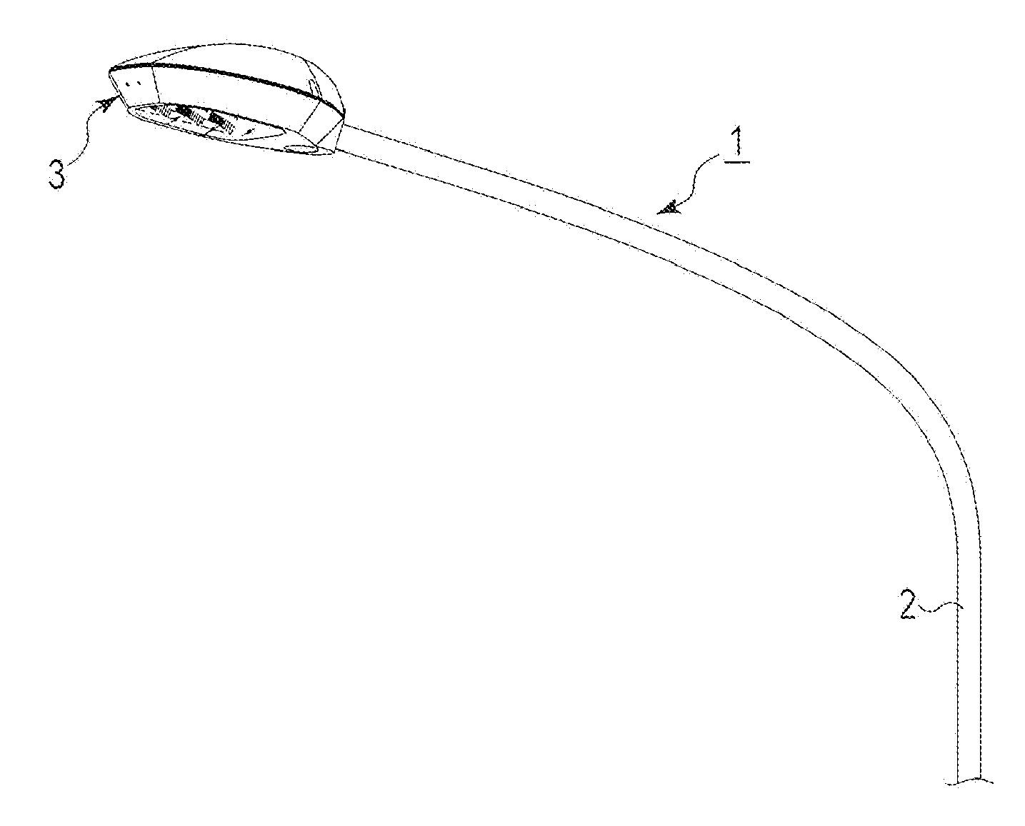
a technology of light-emitting modules and lighting apparatuses, which is applied in the direction of point-like light sources, lighting and heating devices, and lighting support devices, etc., and can solve the problems of high manufacturing cost, large wiring pattern number, and large space for all leds to be placed

Inactive Publication Date: 2011-12-29
TOSHIBA LIGHTING & TECH CORP
View PDF4 Cites 12 Cited by
  • Summary
  • Abstract
  • Description
  • Claims
  • Application Information

AI Technical Summary

Benefits of technology

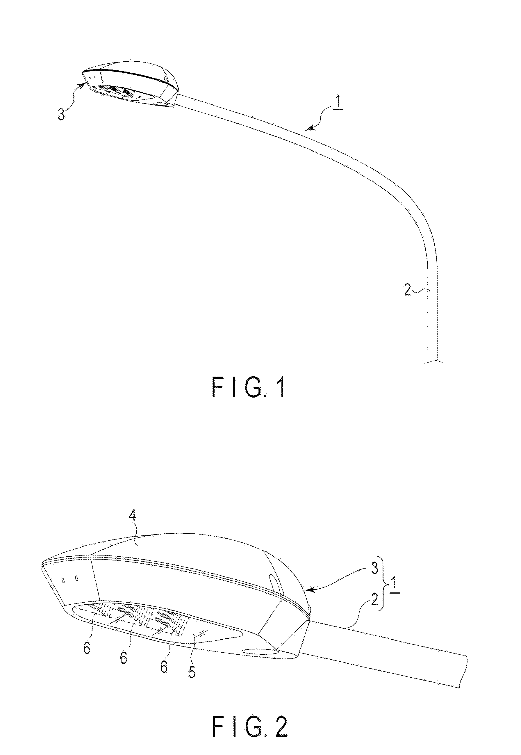
[0040]In the lighting apparatus according to Embodiment 7, the light source device is provided with, as a light source, the light-emitting module according to any one of Embodiments 1 to 6. Thus, an area to provide semiconductor light-emitting element group in this module is small, and the amount of a metal that constitutes wiring patterns can be reduced. Moreover, light can be emitted by the application of a low voltage.

Problems solved by technology

However, the above-mentioned configuration requires a space to keep an insulation distance between adjacent light-emitting systems.
This leads to a greater space to arrange all the LEDs.
Moreover, as the positive and negative wiring patterns are provided for each of the light-emitting systems, the number of wiring patterns is great, which is one of the causes of the high manufacturing costs.
Therefore, the increase of costs is inevitable.

Method used


Image

  • Light-emitting module and lighting apparatus with the same
  • Light-emitting module and lighting apparatus with the same
  • Light-emitting module and lighting apparatus with the same

Examples


Embodiment Construction

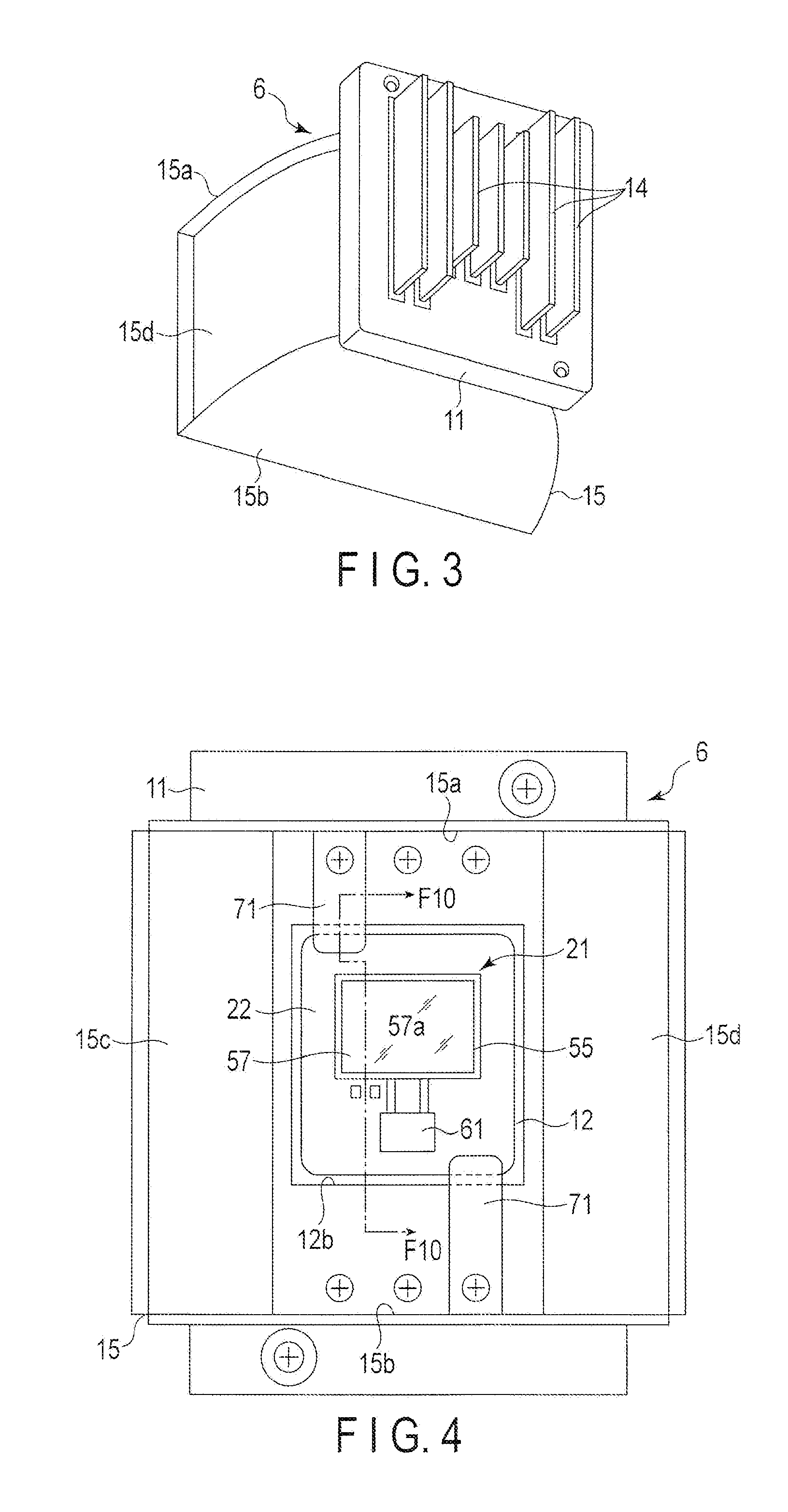
[0020]In general, according to one embodiment, a light-emitting module comprises: a module: substrate; a first wiring pattern provided on the module substrate and having a common wire connecting portion; a second wiring pattern provided on the module substrate around the first wiring pattern and opposite in polarity from the first wiring pattern, the second wiring pattern having a first wire connecting portion which defines a first element arrangement area between the first wire connecting portion and the common wire connecting portion, a second wire connecting portion which is opposite to the first wire connecting portion across the common wire connecting portion and which defines a second element arrangement area between the second wire connecting portion and the common wire connecting portion, and a middle pattern portion connecting the first wire connecting portion to the second wire connecting portion; a first light-emitting element group arranged in the first element arrangeme...


PUM


Abstract

According to one embodiment, a light-emitting module includes a module substrate, a first wiring pattern provided on the module substrate and including a common wire connecting portion, a second wiring pattern provided on the module substrate and including a first wire connecting portion, a second wire connecting portion, and a middle pattern portion, a first light-emitting element group arranged between the common wire connecting portion and the first wire connecting portion and including semiconductor light-emitting elements connected in series and being electrically connected to the common wire connecting portion and the first wire connecting portion, and a second light-emitting element group arranged between the common wire connecting portion and the second wire connecting portion and including semiconductor light-emitting elements connected in series and being electrically connected to the common wire connecting portion and the second wire connecting portion.

Description

CROSS-REFERENCE TO RELATED APPLICATIONS[0001]This application is based upon and claims the benefit of priority from Japanese Patent Applications No. 2010-146730, filed Jun. 28, 2010; No. 2010-146733, filed Jun. 28, 2010; and No. 2010-150418, filed Jun. 30, 2010; the entire contents of all of which are incorporated herein by reference.FIELD[0002]Embodiments described herein relate generally to a light-emitting module suitably usable for, for example, a light source, and a lighting apparatus such as a streetlamp comprising the light-emitting module as a light source.BACKGROUND[0003]A chip-on-board (COB) type light-emitting module having the following configuration is proposed. Positive and negative wiring patterns are alternately provided on a module substrate. Semiconductor light-emitting elements connected in series such as chip-shaped light-emitting diodes (LEDs) are arranged between a pair of positive and negative wiring patterns. These LEDs are electrically connected to the wirin...

Claims


Application Information

Patent Timeline
Patent Type & Authority Applications(United States)
IPC IPC(8): F21V7/00F21S4/00H05B44/00
CPCH05B33/0806H05B45/30
Inventor OYAIZU, TSUYOSHITAKEI, HARUKISAITO, AKIKOKAWASHIMA, SEIKO
Owner TOSHIBA LIGHTING & TECH CORP
Why Eureka
Eureka Blog
Learn More