Clamp

a technology of clamping and spring, which is applied in the field of clamping, can solve the problems of increased production costs, troublesome assembly, and difficult assembly of clamping, and achieve the effect of reducing manufacturing costs and being easy to assembl

Inactive Publication Date: 2008-04-15
PIOLAX CO LTD
View PDF6 Cites 13 Cited by
  • Summary
  • Abstract
  • Description
  • Claims
  • Application Information

AI Technical Summary

Benefits of technology

[0008]Embodiments of the present invention have been developed in view of the above-mentioned and / or other problems in the related art. Among other advantages, some embodiments provide a clamp that is easy to assemble, some embodiments provide a clamp capable of inserting a boss portion of a garnish into the inside of the clamp without using tools, and some embodiments have reduced manufacturing costs.
[0010]With this embodiment, although the clamp is constituted by the synthetic resin clip and the metal plate spring, the plate spring is a generally flat in cross-section. Therefore, as compared to a conventional clamp, the attaching operation for attaching the plate spring to the clip can be performed easily. Furthermore, at the time of inserting a boss portion of a mounting member into the inside of the clip, the insertion operation can be performed by simply inserting the boss portion between the pull-out preventing tongue of the plate spring and the press-fitting craw portion of the other side wall. Thus, the operation can be performed by hand without using any tools. Furthermore, the amount of the metal plate spring can be decreased, resulting in reduced manufacturing costs.
[0012]In this case, when the clip is inserted in the mounting hole of the panel, the inwardly protruded portion formed at the free end of the other side wall comes into contact with the boss portion of the mounting member to prevent the inward deformation of the other side wall. Thus, it becomes possible to prevent such drawbacks that the boss portion of the mounting member can be pulled out of the mounting hole of the panel under the prescribed pulling force or the clamp remains at the mounting hole of the panel by detaching from the boss portion of the mounting member at the time of pulling the boss portion from the mounting hole of the panel.
[0016]According to another aspect, the one side wall is provided with a pair of spring holding portions for holding upper and lower edge portions of the plate spring, and the spring holding portions are disposed horizontally so that the plate spring is inserted between the spring holding portions from the lateral direction. With this structure, the plate spring would not be moved in the vertical direction, and therefore detachment of the plate spring from the one side wall can be prevented at the time of pulling out the boss portion of the mounting member from the mounting hole of the panel.

Problems solved by technology

In such conventional clamp, assembling the clamp, especially fitting the plate spring into the inside of the clip, was troublesome.
Although the fact that the plate spring is of a U-shape in cross-section is one factor, the plate spring should be fitted into the clip by forcibly getting over the engaging portions formed on both inner surfaces of the side walls of the clip, which makes it difficult to assemble.
Furthermore, in the case of inserting the boss portion of the garnish into the inside of the U-shaped plate spring, since the insertion operation cannot be performed by hand, tools are required, resulting in a troublesome insertion operation.
Furthermore, since the metal plate spring is relatively expensive, the U-shaped spring causes increased production costs.

Method used


Image

  • Clamp
  • Clamp
  • Clamp

Examples


Embodiment Construction

[0031]In the following paragraphs, some preferred embodiments of the invention will be described by way of example and not limitation. It should be understood based on this disclosure that various other modifications can be made by those in the art based on these illustrated embodiments.

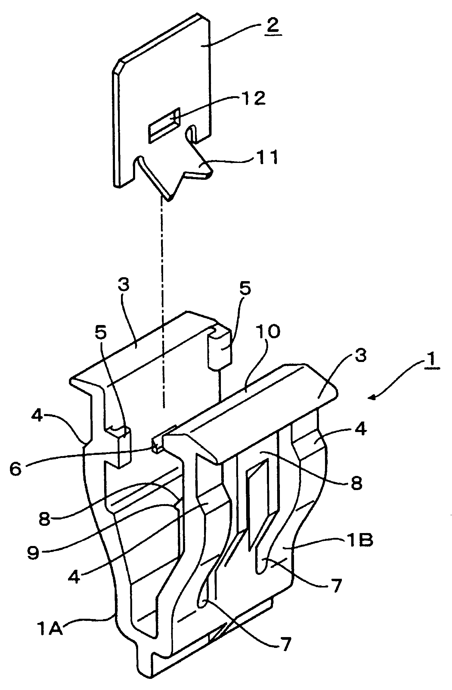
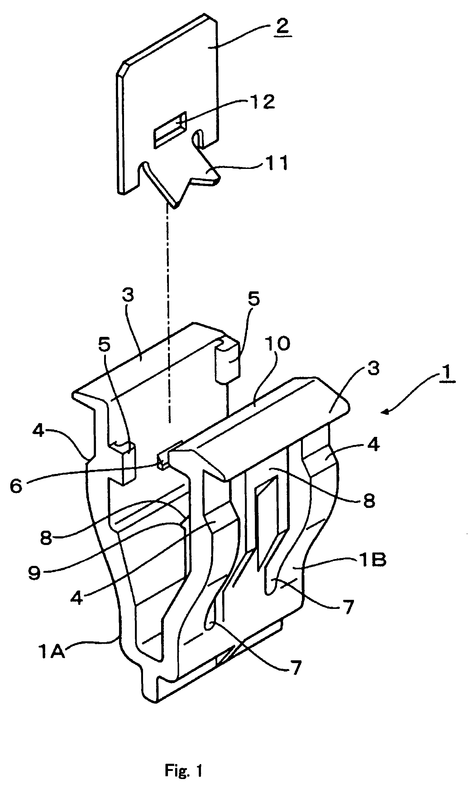
[0032]A clamp according to a first embodiment is used to secure a garnish of an automobile to an automotive body panel having mounting holes utilizing boss portions protruded from the rear surface of the garnish. As shown in FIG. 1, for example, the clamp is basically constituted by two members, i.e., a synthetic clip 1 of a generally U-shape in cross-section and a metal plate spring 2 of a generally flat shape in cross-section.

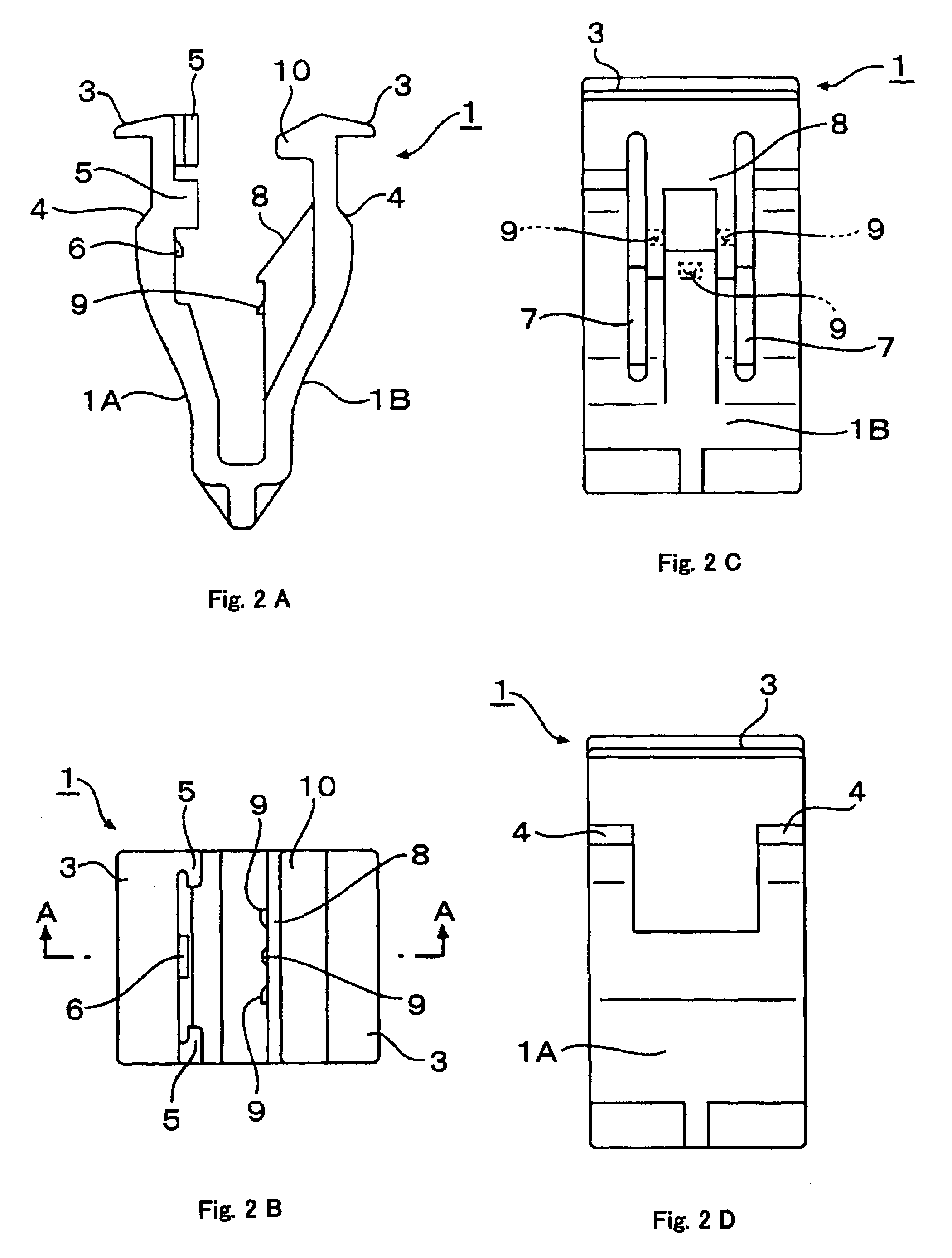
[0033]As shown in FIGS. 2 and 3, for example, the clip 1 is provided with a pair of opposing side walls 1A and 1B each having a flange portion 3 outwardly protruded from the free end of the side wall and an engaging shoulder portion 4 formed on the external surface of the side...


PUM


Abstract

A clamp is provided having a synthetic clip and a metal plate spring. The clip includes a pair of side walls opposed each other at a certain distance, engaging shoulder portions each formed at an outer surface of each of the side walls and configured to be engaged with a peripheral edge of a mounting hole of a panel at the time of securing a mounting member to the panel. The spring is attached to one of the side walls of the clip. A press-fitting craw portion is formed at an inner surface of the other side wall and configured to be pressed against a boss portion of the mounting member. The spring includes a pull-out preventing tongue facing the craw portion and configured to bite into the boss portion of the mounting member at the time of securing the mounting member to the panel.

Description

[0001]This application claims priority under 35 U.S.C. §119 to Japanese Patent Application No. 2005-116517, filed on Apr. 14, 2005, the disclosure of which is incorporated herein by reference in its entirety.FIELD OF THE INVENTION[0002]The present invention relates to a clamp, more specifically to a clamp for securing, for example, a mounting member such as a garnish of an automobile to an automotive body panel having a mounting hole utilizing bosses protruded from the rear surface of the mounting member.BACKGROUND OF THE INVENTION[0003]The following description sets forth the inventor's knowledge of related art and problems therein and should not be construed as an admission of knowledge in the prior art.[0004]A conventional clamp is constituted of two members, i.e., a synthetic resin clip of a generally U-shape in cross-section and a metal plate spring of a generally U-shape in cross-section fitted inside the clip (e.g., Japanese Design Registration No. 1,212,949.) The clip includ...

Claims


Application Information

Patent Timeline
Patent Type & Authority Patents(United States)
IPC IPC(8): F16B5/06
CPCB60R13/0206B60R13/04F16B5/065F16B21/075F16B21/078F16B5/0657Y10T24/309Y10T24/42
Inventor OKADA, SHIGEO
Owner PIOLAX CO LTD
Why Eureka
Try Eureka