Control rod/fuel support handling apparatus

a technology of handling apparatus and control rod, which is applied in the direction of nuclear elements, climate sustainability, greenhouse gas reduction, etc., can solve the problems of increased operation time, difficulty in lifting the lock plug, and human error or erroneous confirmation, so as to reduce the replacement time of the control rod

Active Publication Date: 2011-12-29
KK TOSHIBA
View PDF3 Cites 9 Cited by
  • Summary
  • Abstract
  • Description
  • Claims
  • Application Information

AI Technical Summary

Benefits of technology

[0012]In view of the above circumstances, an object of the present invention is to provide a control rod / fuel support handling apparatus which can reliably connect and disconnect a control rod and a control rod drive mechanism via a bayonet coupling without causing human errors or erroneous confirmation.
[0013]Another object of the present invention is to provide a control rod / fuel support handling apparatus which can considerably reduce a replacement time of a control rod by simultaneously removing or attaching the control rod and a fuel support.
[0024]Moreover, the fuel support gripper that is supported by the suspension wire so as to remove and attach the fuel support contains the control rod gripper allowing removal and attachment of the control rod. Thus the control rod and the fuel support can be simultaneously removed or attached, considerably reducing a replacement time of the control rod.

Problems solved by technology

Thus unfortunately, if a foreign matter such as crud is caught between the lock plug 12 and the coupling spud 11, it is difficult to lift the lock plug 12 and the control rod 4 and the control rod drive mechanism 8 may not be disconnected from each other.
Unfortunately, in the control rod / fuel support gripper of patent document 1, the control rod 4 and a control rod drive mechanism 8 are connected and disconnected via a bayonet coupling by human decisions and thus a human error or erroneous confirmation may occur.
Thus backtracking is necessary for confirmation and correction of such errors, so that an operation time increases accordingly and affects a critical process.

Method used


Image

  • Control rod/fuel support handling apparatus
  • Control rod/fuel support handling apparatus
  • Control rod/fuel support handling apparatus

Examples


Embodiment Construction

[0045]A best mode for carrying out the present invention will be described below in accordance with the accompanying drawings. The present invention is not limited to the following embodiments. Further, it should be noted that terms describing directions such as vertical and lateral directions and orientations in specifications are expressed based on illustrated states or actual operating states.

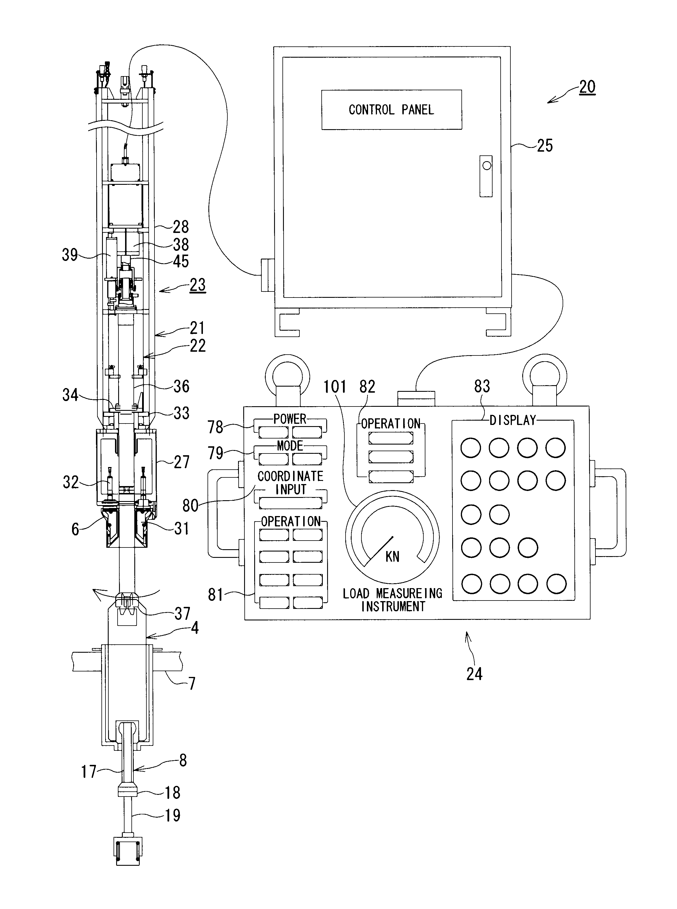
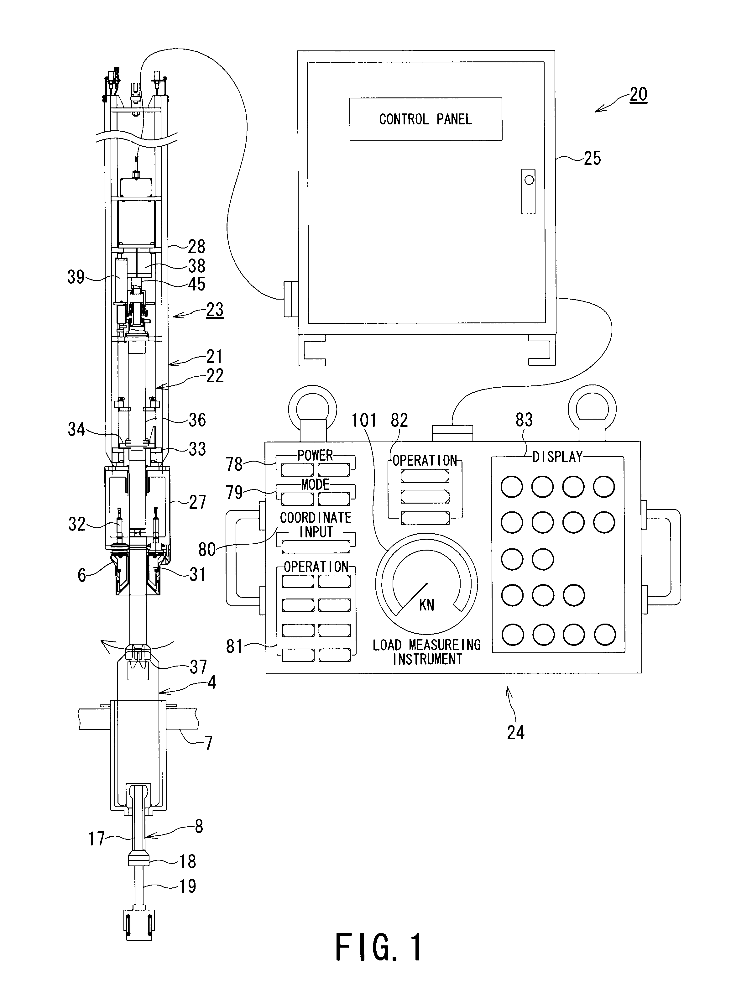
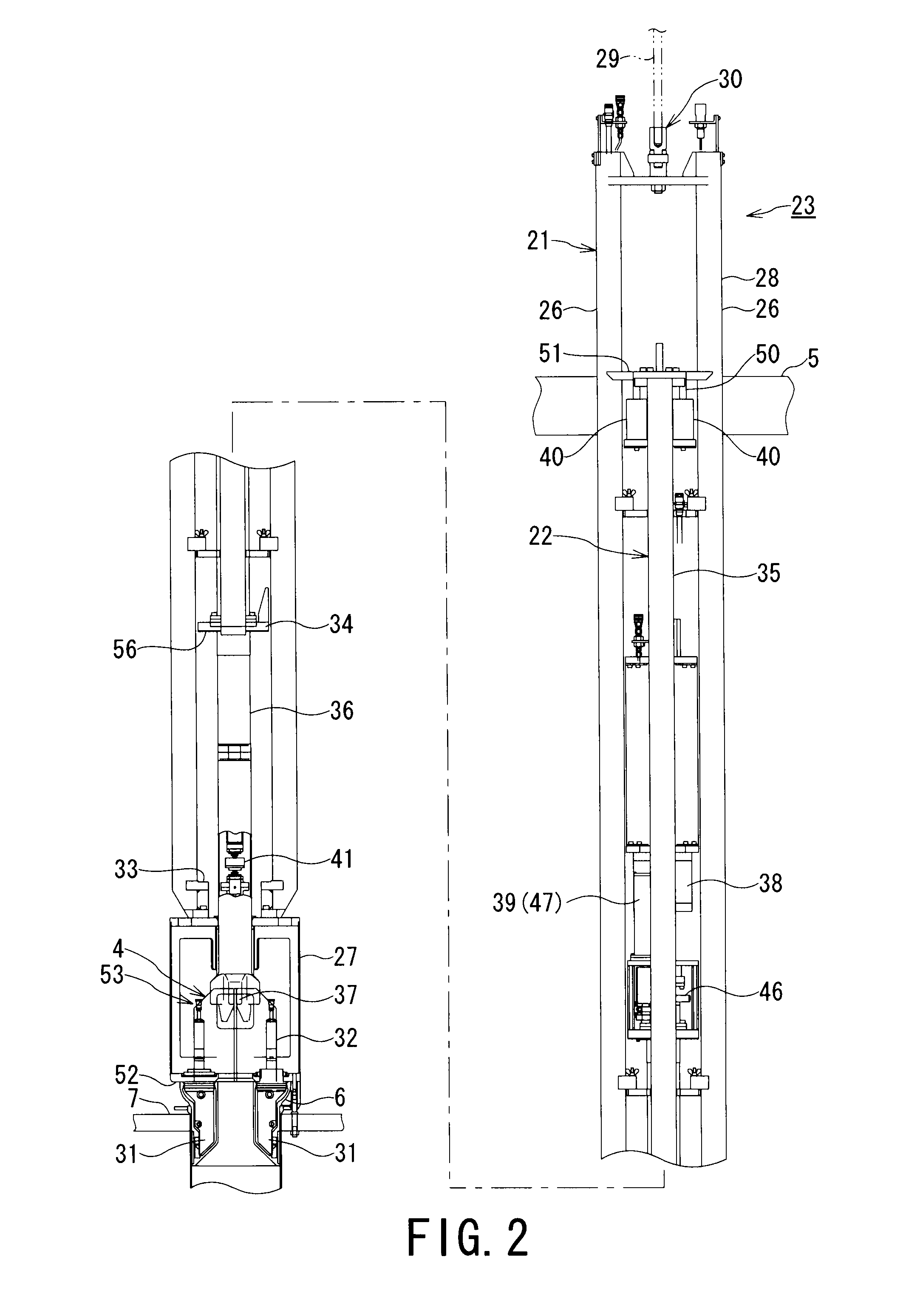
[0046]FIG. 1 is a structural diagram showing an embodiment of a control rod / fuel support handling apparatus according to the present invention. FIG. 2 is a side view showing a sitting state in a gripper assembly of a fuel support gripper and a control rod gripper of FIG. 1. FIG. 4 is a side view showing the control rod gripper of FIG. 1. In the present embodiment, the same parts as in drawings of the related art will be indicated by the same reference numerals and the explanation thereof is simplified or omitted.

[0047]A control rod / fuel support handling apparatus 20 in FIG. 1 is used for sim...


PUM


Abstract

A control rod / fuel support handling apparatus that is used in the case where a control rod and a fuel support are held, removed and lifted in a reactor and then are transported into the reactor in a periodical inspection of a BWR and in the case where the control rod and the fuel support are attached and mounted again into the reactor, the control rod / fuel support handling apparatus including: a fuel support gripper that holds the fuel support with a support gripping member; a control rod gripper that includes a vertically movable and rotatable elevating / rotating unit, holds the control rod with a control rod gripping member, disconnects and connects the control rod and a control rod drive mechanism, and allows removal and attachment of the control rod; and a control panel that controls automatically controls the control rod gripper in response to the instructions from an operation pendant.

Description

TECHNICAL FIELD[0001]The present invention relates to a control rod / fuel support handling apparatus that is used in the case where a control rod and a fuel support are held, removed and lifted in a reactor and then are transported into the reactor in a periodical inspection of a boiling water reactor (BWR) and in the case where the control rod and the fuel support are attached and mounted again in the reactor.BACKGROUND ART[0002]As shown in FIG. 18, a reactor core of a BWR is typically configured such that a cylindrical reactor-core shroud 2 is provided in a reactor pressure vessel 1 and fuel assemblies 3 and control rods 4 are mounted in the reactor-core shroud 2. The fuel assemblies 3 each have an upper part supported by a upper guide 5 and a lower part supported by a core plate 7 via a fuel support 6. A coolant flows into each of the fuel assemblies 3 from an orifice hole 6A of the fuel support 6.[0003]The control rod 4 is connected to a control rod drive mechanism 8 penetrating ...

Claims


Application Information

Patent Timeline
Patent Type & Authority Applications(United States)
IPC IPC(8): G21C19/19
CPCG21C19/105G21C19/207G21C19/19Y02E30/30
Inventor TOMATSU, TSUTOMUSOMA, KOICHITAKAGI, KAORU
Owner KK TOSHIBA
Why Eureka
Try Eureka