
Turbine stage

a technology of turbine stage and casing rail, which is applied in the direction of machines/engines, stators, liquid fuel engines, etc., can solve the problems of reducing the lifetime of the casing rail, the casing rail is creeping, and the casing rail is prone to slipping, etc., to achieve the effect of simple, effective and inexpensiv

Active Publication Date: 2011-12-29
SN DETUDE & DE CONSTR DE MOTEURS DAVIATION S N E C M A
View PDF4 Cites 5 Cited by
  • Summary
  • Abstract
  • Description
  • Claims
  • Application Information

AI Technical Summary

Benefits of technology

[0007]A particular object of the invention is to provide a solution to these problems that is simple, effective, and inexpensive.
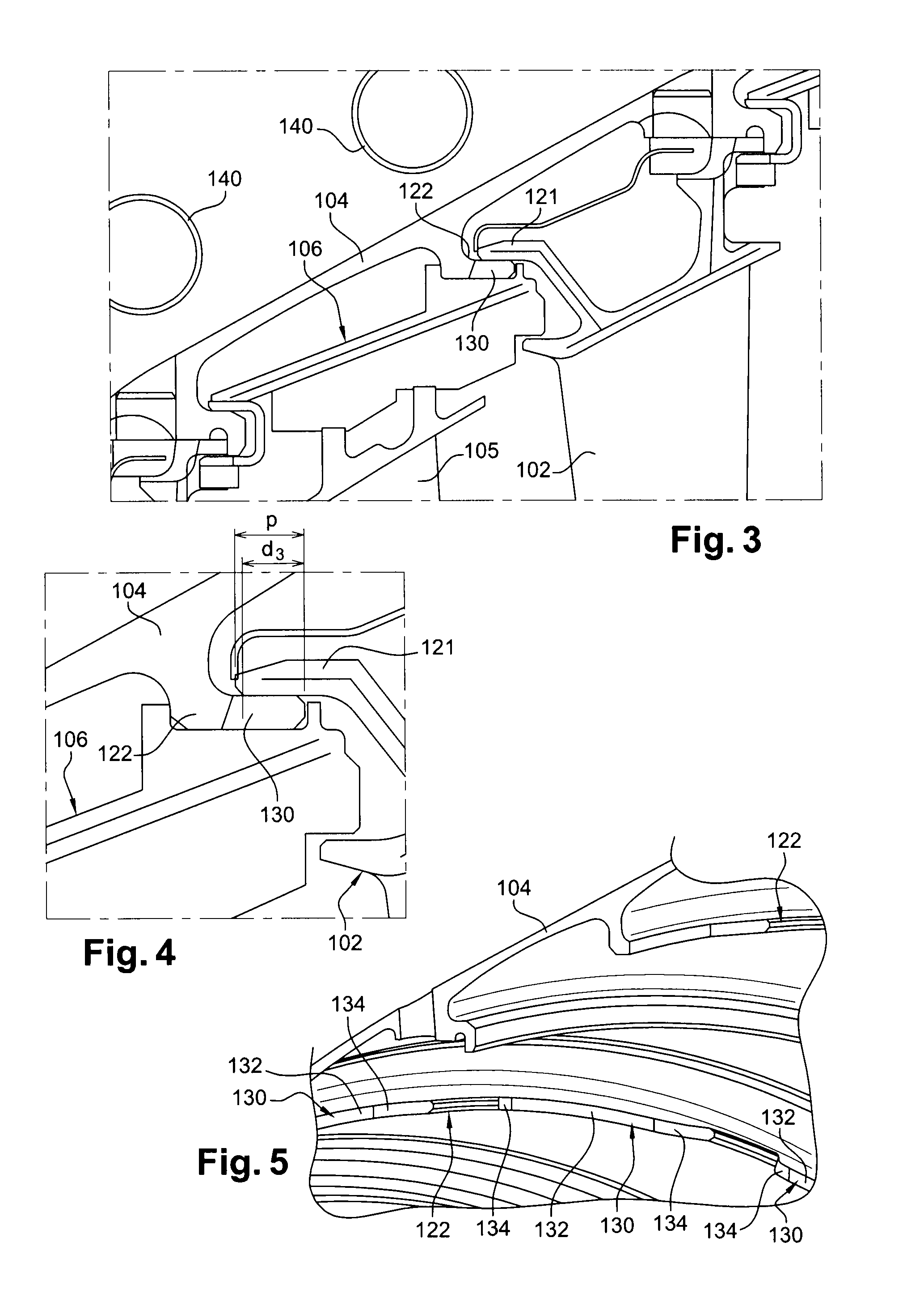
[0008]To this end, the invention provides a turbine stage for a turbomachine such as an airplane turboprop or turbojet, the stage comprising a rotor wheel mounted inside a sectorized ring carried by an outer casing, and a sectorized nozzle fastened to the casing downstream from the wheel, each ring sector having a downstream end that is held bearing radially outwards against a cylindrical rail of the casing by means of the nozzle, wherein the casing rail includes an annular row of through radial notches reducing the areas for heat exchange by conduction both between the casing and the ring sectors and between the casing and the nozzle.
[0010]Providing through radial notches in the cylindrical rail of the casing serves to reduce the contact areas both between the casing rail and of the ring sectors and between the casing rail and the nozzle sectors, thereby serving in operation to eliminate the heating by thermal conduction of the casing rail, and more generally of the outer casing. Furthermore, the notches serve to lighten the casing and to concentrate the above-mentioned tangential stresses in the ends of the notches, i.e. in zones that are spaced apart from the end portion of the rail and that are therefore less exposed to high temperatures.
[0016]Advantageously, the end walls of the notches are outwardly inclined from upstream to downstream in order to obtain better control over the distribution of the above-mentioned tangential stresses.

Problems solved by technology

The casing may thus reach a high temperature that runs the risk of weakening it and of shortening its lifetime.
Furthermore, in operation, the nozzle sectors transmit forces to the casing rail, which rail is subjected to relatively large tangential stresses in its downstream end portion, thereby giving rise to a phenomenon of creep in the casing rail.
These tangential stresses are in addition to the above-mentioned thermal stresses and they reduce the lifetime of the casing rail considerably.

Method used


Image

  • Turbine stage
  • Turbine stage
  • Turbine stage

Examples


Embodiment Construction

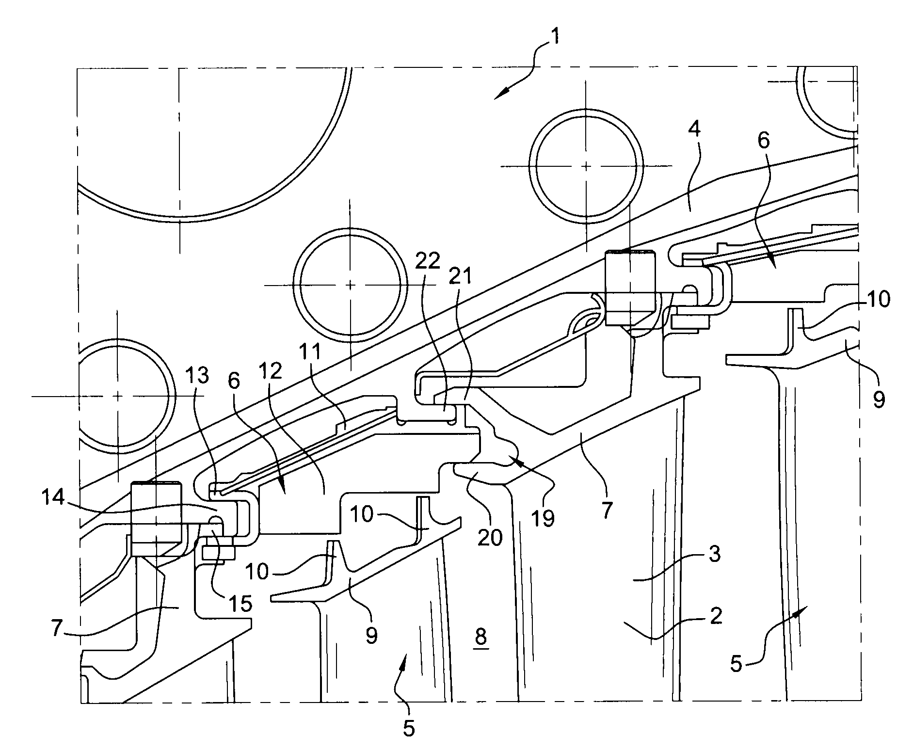
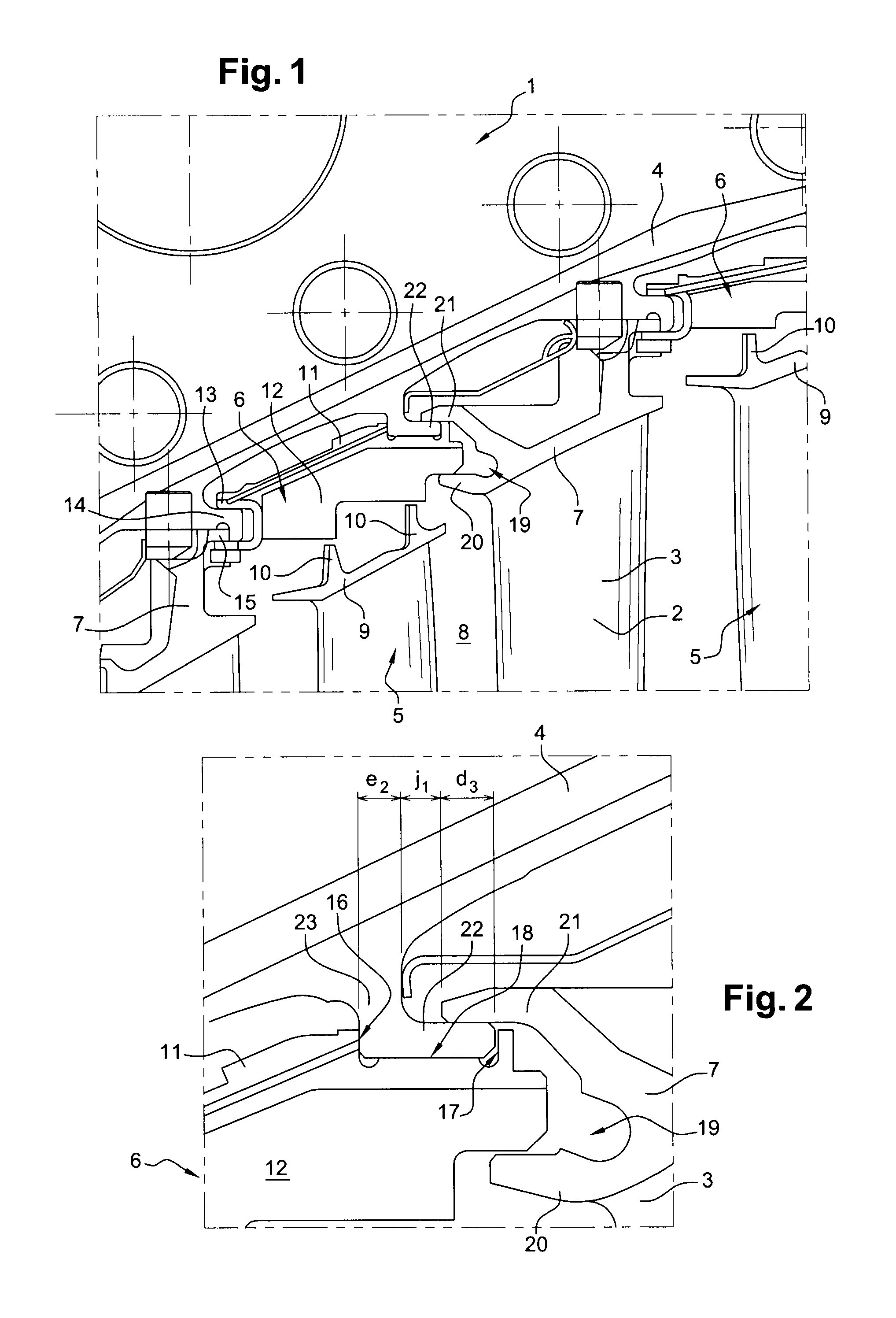
[0027]FIGS. 1 and 2 show a low-pressure turbine 1 in a prior art turbomachine, comprising a plurality of stages each having a nozzle 2 carried by an outer casing 4 of the turbine and a rotor wheel 5 is mounted upstream from the nozzle 2 to rotate in a substantially frustoconical ring formed by sectors 6 carried circumferentially end to end by the casing 4 of the turbine.

[0028]The nozzles 2 have inner walls (not shown) and outer walls 7 forming surfaces of revolution that define between them an annular passage 8 for passing gas through the turbine and that are connected together radially by vanes 3.

[0029]The rotor wheels 5 are secured to a turbine shaft (not shown), and each of them comprises outer platforms 9 and inner platforms (not shown), the outer platform 9 having outer radial ribs 10 surrounded on the outside with small clearance by the ring sectors 6.

[0030]Each ring sector 6 has a frustoconical wall 11 and a block of abradable material 12 fastened to the radially inside surfa...


PUM


Abstract

A turbine stage for a turbomachine, the stage comprising a rotor wheel mounted inside a sectorized ring carried by an outer casing, and a sectorized nozzle fastened to the casing downstream from the wheel, each ring sector having a downstream end that is held bearing radially outwards against a cylindrical rail of the casing by means of the nozzle, the casing rail including an annular row of through radial notches reducing the areas for heat exchange by conduction both between the casing and the ring sectors and between the casing and the nozzle.

Description

FIELD OF THE INVENTION[0001]The present invention relates to a turbine stage of a turbomachine such as an airplane turboprop or turbojet.BACKGROUND OF THE INVENTION[0002]A turbomachine turbine, in particular a low-pressure turbine, comprises a plurality of stages, each having a rotor wheel mounted to rotate in a cylindrical or frustoconical ring formed by sectors that are fastened together end to end circumferentially on an outer casing of the turbine, and a nozzle located downstream from the wheel and formed by an annular row of stationery vanes carried by the outer casing (FR-A1-2 899 273 in the name of the Applicant).[0003]Hot gas under pressure leaving the combustion chamber of the turbomachine passes between the vanes of the nozzles and flows over the blades of the turbine wheels, thereby having the effect of raising the temperature of the rings.[0004]In known manner, each ring sector presents a downstream end that is kept bearing radially against a cylindrical casing rail via ...

Claims


Application Information

Patent Timeline
IPC IPC(8): F01D25/16
CPCF01D11/12Y02T50/671F01D25/246Y02T50/60
Inventor GARIN, FABRICE MARCEL NOELGENDRAUD, ALAIN DOMINIQUELEQUITTE, THIERRYPRESTEL, SEBASTIEN JEAN LAURENT
Owner SN DETUDE & DE CONSTR DE MOTEURS DAVIATION S N E C M A
Learn More