Implementing substation automation load transfer function

a load transfer and substation technology, applied in the field of substation automation (sa) systems, can solve problems such as complex logic requirements

Active Publication Date: 2011-12-29
HITACHI ENERGY SWITZERLAND AG
View PDF5 Cites 49 Cited by
  • Summary
  • Abstract
  • Description
  • Claims
  • Application Information

AI Technical Summary

Problems solved by technology

A failure at one of the in-feeds leads to a protection trip disconnecting this in-feed.
In more complex bus bar situations a complex logic is required, the implementation and testing of which is specific for each project or single line diagram, as well as error prone due to the complexity.

Method used


Image

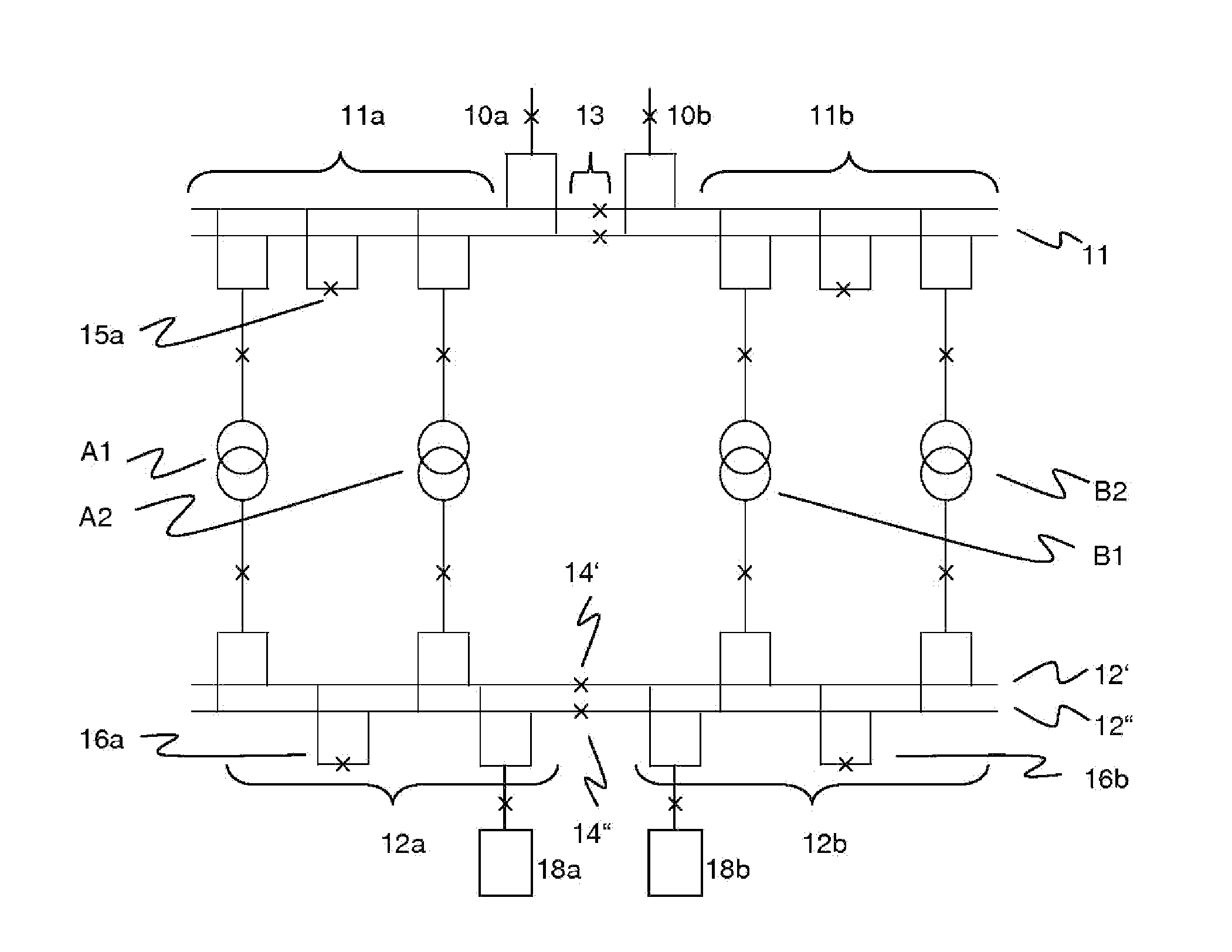
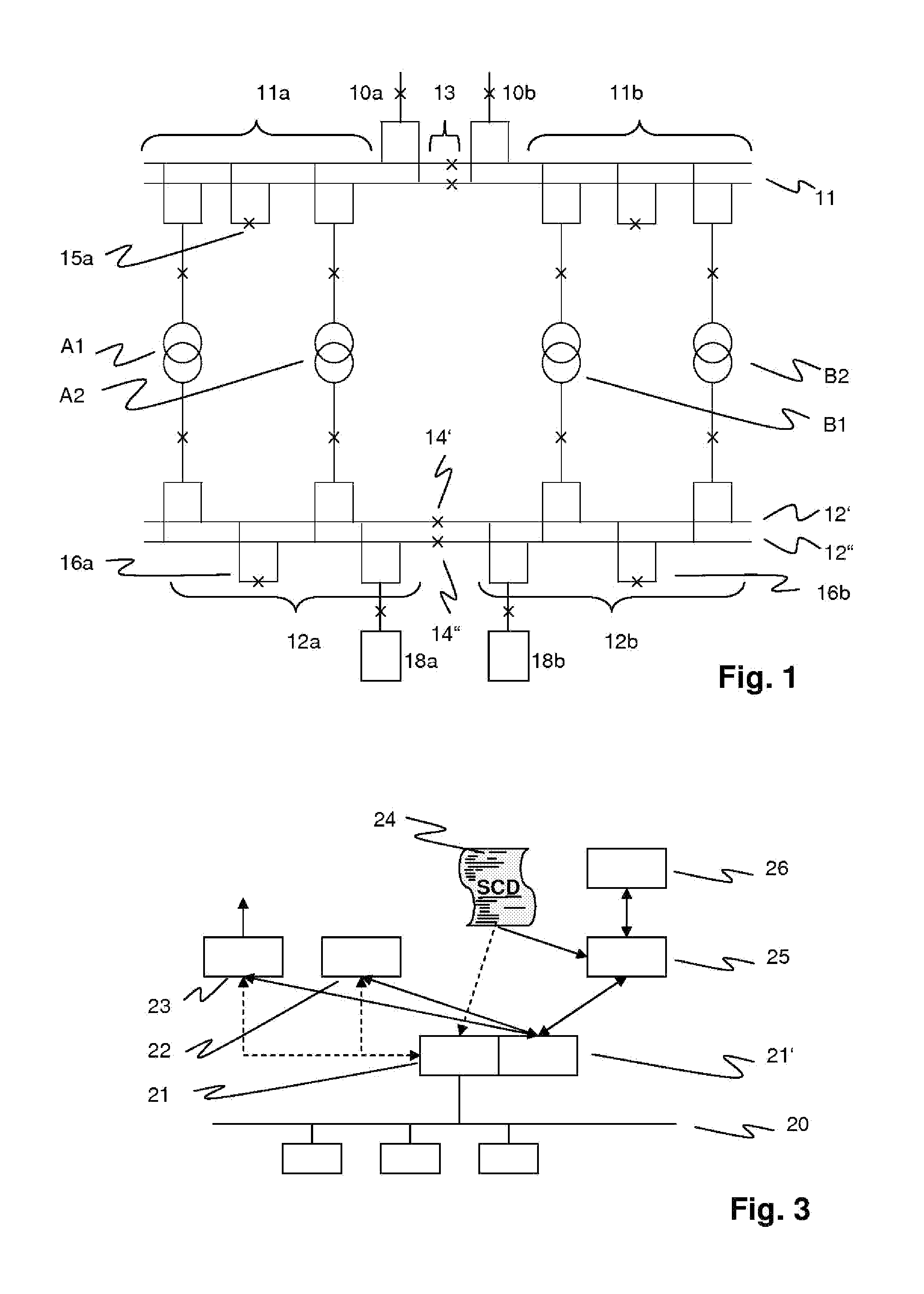
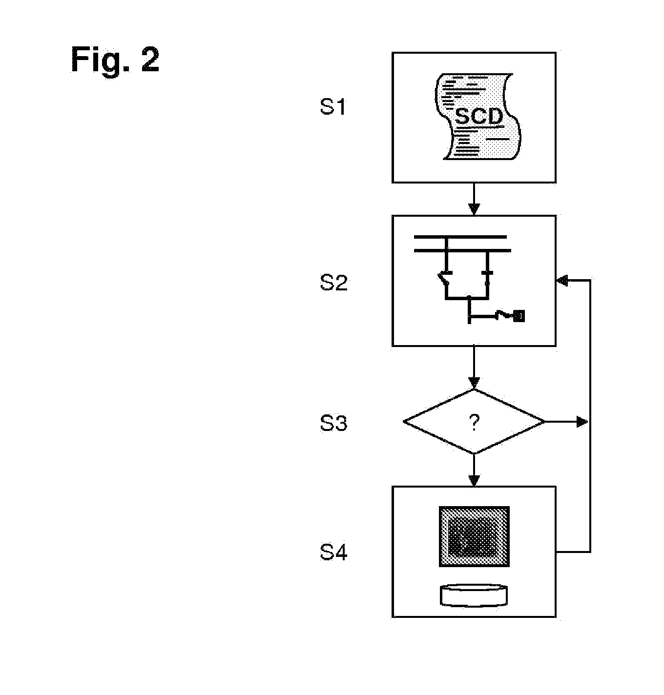
  • Implementing substation automation load transfer function
  • Implementing substation automation load transfer function
  • Implementing substation automation load transfer function

Examples


Embodiment Construction

[0019]It is therefore an objective of the exemplary embodiments of the present disclosure to simplify the implementation of load transfer functions in SA systems.

[0020]According to exemplary embodiments of the present disclosure, a method of implementing, or establishing, a load transfer function in a Substation Automation SA system for an electric power transmission / distribution substation supplying power to a number of loads and includes first and second, or high and medium voltage, bus bars interconnected by transformers. The method includes the steps of reading a standardized configuration description of the SA system, and obtaining therefrom a static topology representative of at least a part of the substation as well as information about primary elements, in particular switching devices, of the substation, and repeatedly, or continually, updating a dynamic instantaneous substation topology representative of at least said part of the substation, based on a switch status of a nu...


PUM


Abstract

A process of implementing, or engineering, topology-dependent functions based on a formal description of the Substation Automation system, includes performing a topology analysis of the current single line state. A topology interpreting implementation replacing complex topology analysis logics can include the project specific static single line topology and the connection to the real process state data. All information can be delivered in an IEC 61850 conforming SCD file. The interface description for controlling and monitoring the load transfer application can be generated automatically from the SCD file.

Description

RELATED APPLICATION[0001]This application claims priority under 35 U.S.C. §119 to European Patent Application No. 10167226.9 filed in Europe on Jun. 24, 2010, the entire content of which is hereby incorporated by reference in its entirety.FIELD[0002]The disclosure relates to the field of Substation Automation (SA) systems with a standardized configuration representation. More particularly, it relates to a method of implementing a load transfer function.BACKGROUND INFORMATION[0003]Substations in high and medium-voltage power networks include primary devices such as electrical cables, lines, bus bars, switches, power transformers and instrument transformers, which are generally arranged in switch yards and / or bays. These primary devices are operated in an automated way via a Substation Automation (SA) system. The SA system includes secondary devices, among which Intelligent Electronic Devices (IED) responsible for protection, control and monitoring of the primary devices. The secondar...

Claims


Application Information

Patent Timeline
Patent Type & Authority Applications(United States)
IPC IPC(8): G06F1/28G16Z99/00
CPCH02J3/006Y04S10/525H02J2003/001G16Z99/00H04B3/54H02J3/0073H02J3/001Y04S10/52H02J3/0012
Inventor RIETMANN, PETERWIMMER, WOLFGANG
Owner HITACHI ENERGY SWITZERLAND AG
Why Eureka
Try Eureka