Method and Apparatus for Simulating an Optical Effect of an Optical Lens

a technology of optical lens and optical effect, applied in the field of optical effect simulating apparatus, can solve the problems of high calculation power, prohibitive cost, and complex system requirements for implementation of virtual simulation method, and achieve the effect of less complex data processing techniques, simplified simulating optical

Active Publication Date: 2012-01-05
ESSILOR INT CIE GEN DOPTIQUE
View PDF0 Cites 6 Cited by
  • Summary
  • Abstract
  • Description
  • Claims
  • Application Information

AI Technical Summary

Benefits of technology

[0007]Accordingly, one object of the present invention is to provide a method of simulating an optical effect of an optical lens which is more simplified, requiring less complex data processing techniques and less complex systems.
[0008]To better address one or more of the foregoing concerns, in accordance with a first aspect of the invention there is provided a method of simulating an optical effect of an optical lens for a potential wearer, the method comprising: using a first camera to take a first image of a scene through a first optical lens, the first optical lens having optical characteristics according to a first ophthalmic lens design, the first camera being provided with optics arranged to simulate the optical characteristics of a human eye; and displaying the first image on a display device for viewing by the potential wearer enabling the potential wearer to visualise the optical effects of the first optical lens on his viewing ability. The position of the second camera, the second optical lens and the first and second screen of the display device are fixed with respect to the referential frame.
[0011]The method may include using a second camera to simultaneously take a second image of the scene through a second optical lens, the second optical lens having optical characteristics according to a second ophthalmic lens design; the second camera being provided with optics arranged to simulate the optical conditions of a human eye such that the first and second camera simulate a pair of human eyes; displaying the first image on a first screen of the display device for viewing by the wearer through a first eye; and displaying the second image simultaneously on a second screen of the display device for simultaneous viewing by the wearer through a second eye, thereby enabling a binocular reconstruction of the first and second images. The position of the second camera, the second optical lens and the first and second screen of the display device are fixed with respect to the referential frame. The second ophthalmic lens design preferably is identical to the first ophthalmic lens design.
[0016]The apparatus may include a second camera being provided with optics arranged to simulate the optical conditions of a human eye such that the first and second camera simulate a pair of human eyes; a second optical lens having optical characteristics according to a second ophthalmic lens design; the second camera being arranged to simultaneously take a second image of the scene through the second optical lens; the display device may include a first screen for displaying the first image for viewing by the potential wearer through a first eye and a second screen for displaying the second image for simultaneous viewing by the potential wearer through a second eye, thereby enabling a binocular reconstruction of the first and second images. The position of the second camera, the second optical lens and the first and second screen of the display device are fixed with respect to the referential frame.

Problems solved by technology

Such techniques suffer the drawback that the wearer has to go through the process of putting off and taking off a number of spectacles and may only be exposed to a limited selection of lenses which may not include the optical lens optimal for correcting the particular eyesight defect.
A drawback of the system described in WO 2007 / 056795 is that it requires complex data processing techniques and a high calculating power to provide an average quality output image.
This leads to prohibitive costs and complex system requirements for implementation of the virtual simulation method.

Method used


Image

  • Method and Apparatus for Simulating an Optical Effect of an Optical Lens
  • Method and Apparatus for Simulating an Optical Effect of an Optical Lens
  • Method and Apparatus for Simulating an Optical Effect of an Optical Lens

Examples


Embodiment Construction

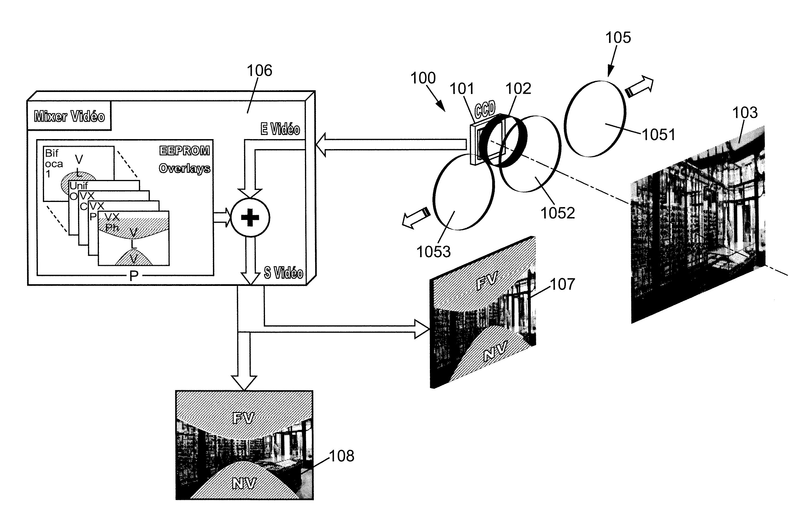
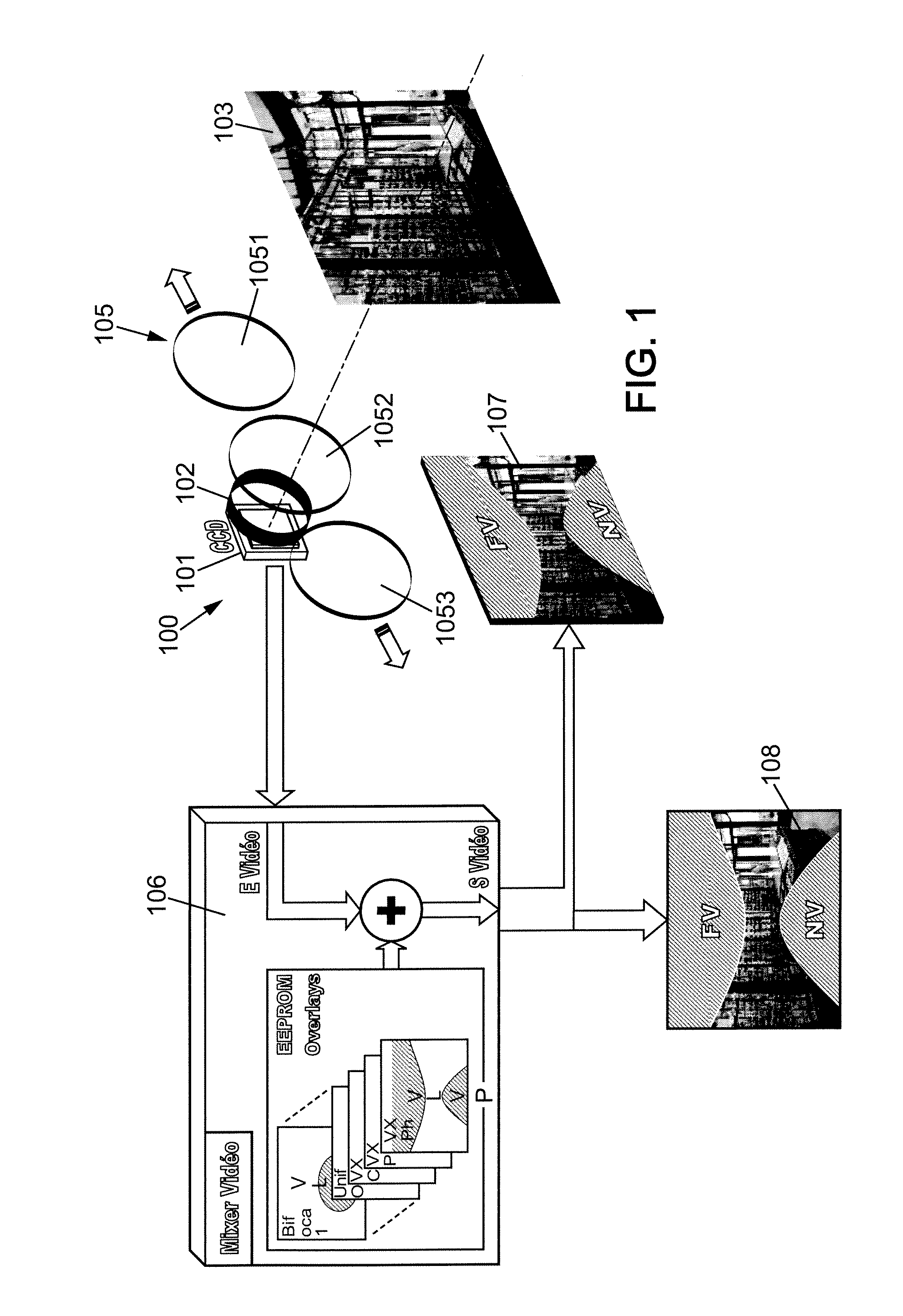
[0037]An apparatus for simulating an optical effect of an optical lens according to a first embodiment of the invention will be described with reference to FIGS. 1 to 4B.

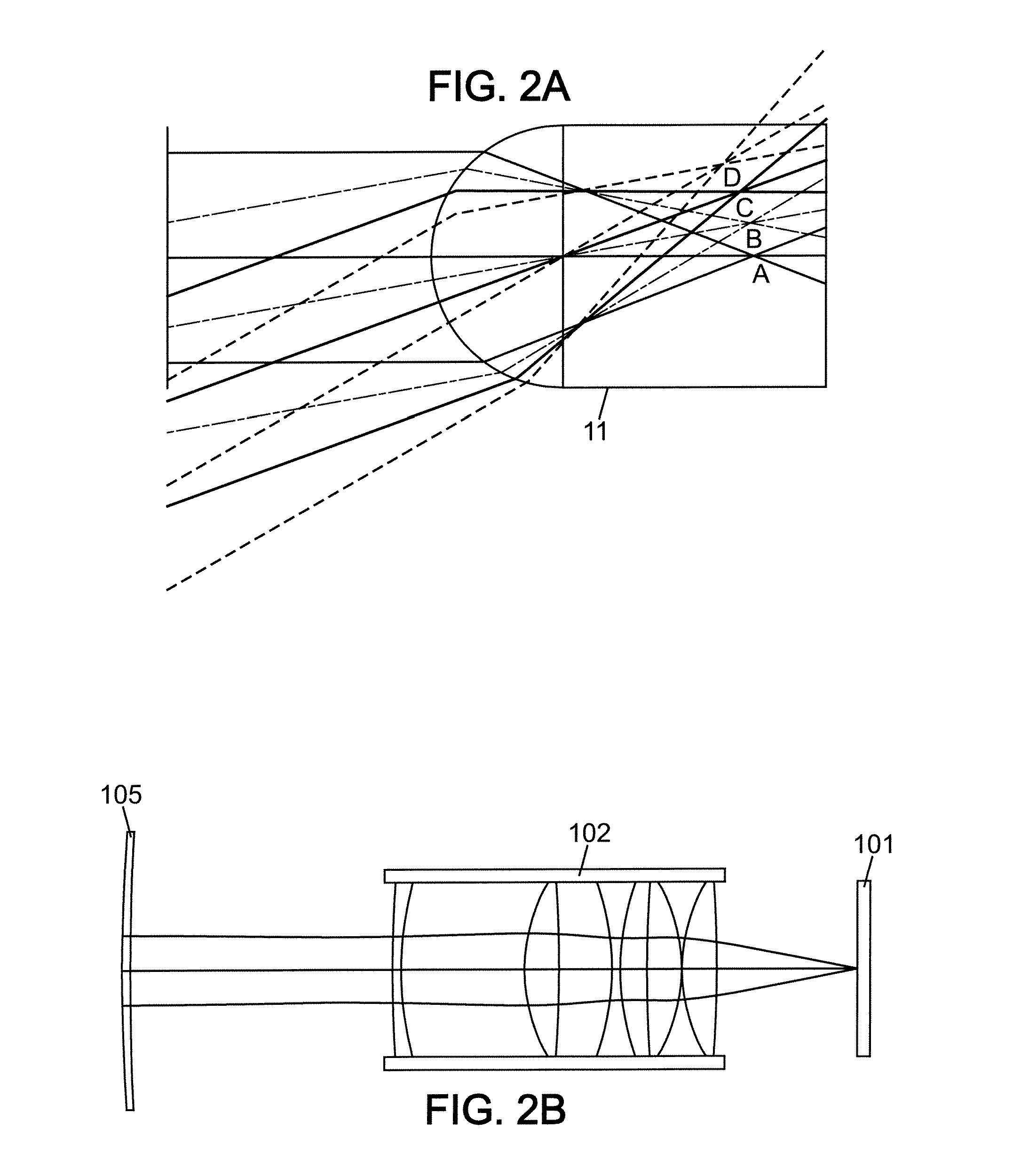
[0038]With reference to FIG. 1, the apparatus 100 for simulating the optical effect of an optical lens includes a CCD (charge coupled device) type video camera 101 provided with camera optics 102 disposed in front of the camera 101, and a plurality of optical lenses 105 supported in front of the camera optics 102 by a barrel (not shown).

[0039]The barrel houses the optical lens 105 to be tested and is arranged such that an optical lens may be interchanged manually or automatically with a different optical lens enabling one optical lens at a time to be placed in front of the camera optics 102. The barrel may hold each optical lens 105 on a circular support which is arranged to rotate to place an individual optical lens in front of the camera optics 102 or it may be of a linear form, in which lenses are placed one by o...


PUM


Abstract

A method of simulating an optical effect of an optical lens for a potential wearer, the method comprising: using a first camera to take a first image of a scene through a first optical lens, the first optical lens having optical characteristics according to a first ophthalmic lens design, the first camera being provided with optics arranged to simulate the optical characteristics of a human eye; and displaying the first image on a display device for viewing by the potential wearer enabling the potential wearer to visualise the optical effects of the first optical lens on his viewing ability. The position of the first camera, the first optical lens and the display device are fixed with respect to a referential frame defined by the head of the potential wearer, the head of the potential wearer being movable with respect to the scene.

Description

RELATED APPLICATIONS[0001]This is a U.S. National Phase Application under 35 USC 371 of International Application PCT / EP2009 / 067600 filed on Dec. 18, 2009.[0002]This application claims the priority of European Application No. 08306000.4 filed Dec. 22, 2008, the entire content of which is hereby incorporated by reference.FIELD OF THE INVENTION[0003]The present invention relates to a method of and an apparatus for simulating an optical effect of an optical lens for a potential wearer.BACKGROUND OF THE INVENTION[0004]Traditionally prescribing ophthalmic lens to a wearer involves fitting a potential wearer having an eyesight defect with ophthalmic lenses having different optical characteristics and then selecting the lenses which provide the best optical performance for the wearer. Such techniques suffer the drawback that the wearer has to go through the process of putting off and taking off a number of spectacles and may only be exposed to a limited selection of lenses which may not in...

Claims


Application Information

Patent Timeline
Patent Type & Authority Applications(United States)
IPC IPC(8): A61B3/02
CPCG01M11/0257
Inventor BONNIN, THIERRY
Owner ESSILOR INT CIE GEN DOPTIQUE
Why Eureka
Try Eureka