Light adjusting apparatus

a technology of light adjusting apparatus and light adjusting blade, which is applied in the direction of mountings, optics, instruments, etc., can solve the problems of diaphragm blade deformation and extremely difficult assembly, and achieve the effect of easy assembly and high product accuracy

Active Publication Date: 2012-01-05
OLYMPUS CORP
View PDF4 Cites 13 Cited by
  • Summary
  • Abstract
  • Description
  • Claims
  • Application Information

AI Technical Summary

Benefits of technology

[0033]According to the present invention, there can be provided a light adjusting apparatus which can be assembled easily and in which, a product-accuracy can be maintained to be high.

Problems solved by technology

Consequently, when an attempt is made to link the shaft and the diaphragm blade by press fitting, there is a possibility of the diaphragm blade getting deformed (in axial direction) at the time of press fitting, and there is a possibility of assembling becoming extremely difficult.

Method used


Image

  • Light adjusting apparatus
  • Light adjusting apparatus
  • Light adjusting apparatus

Examples


first embodiment

[0045]A light adjusting apparatus according to a first embodiment of the present invention will be described below by referring to diagrams from FIG. 1 to FIG. 5.

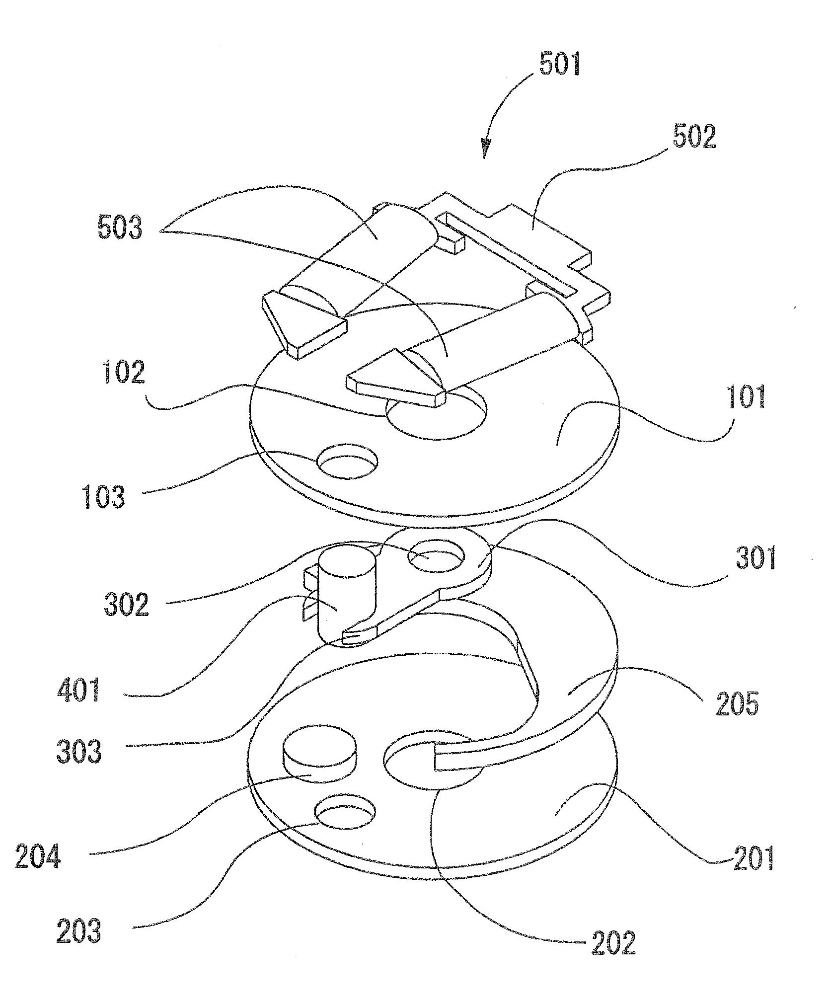
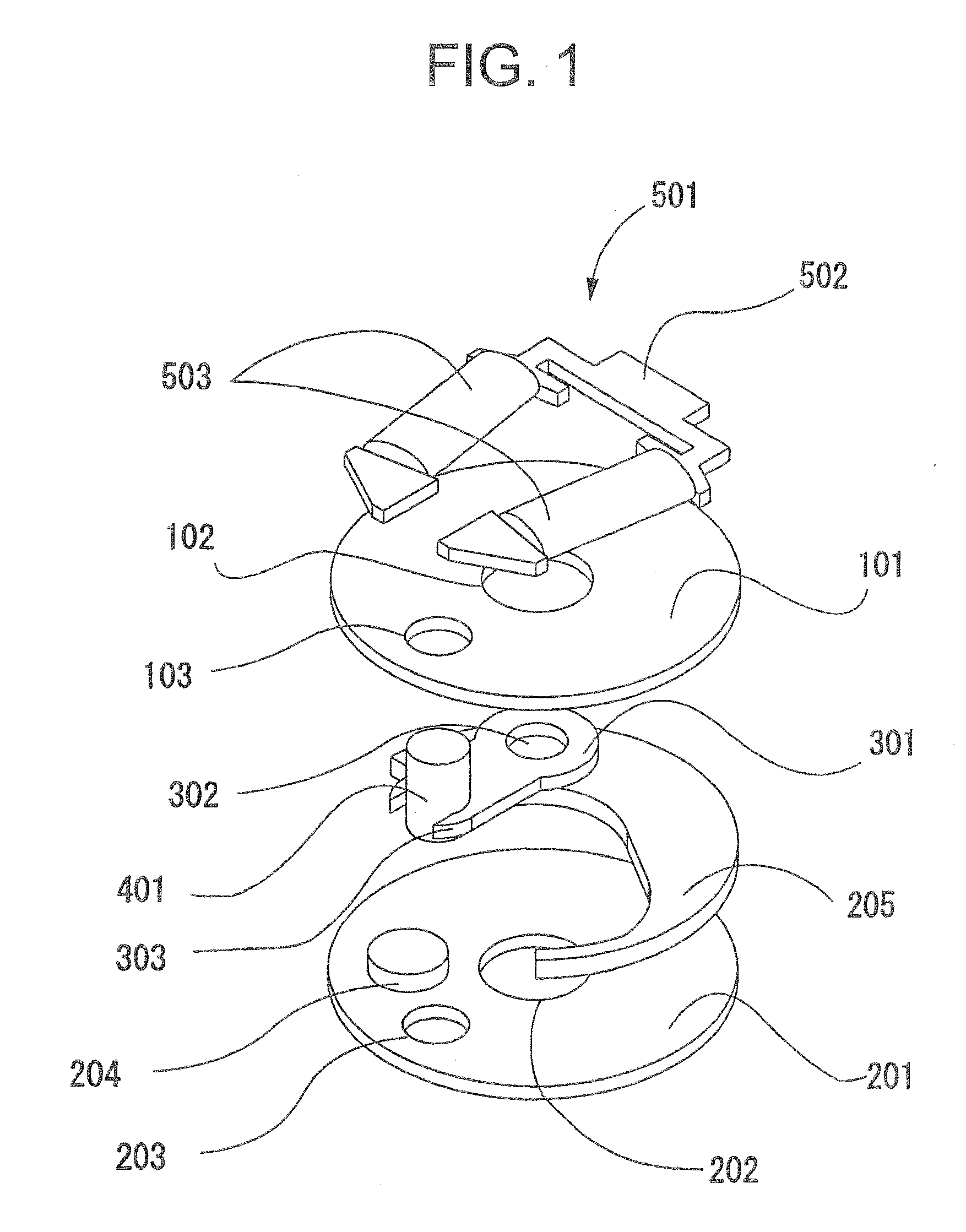
[0046]An exploded perspective view of the light adjusting apparatus according to the first embodiment is shown in FIG. 1.

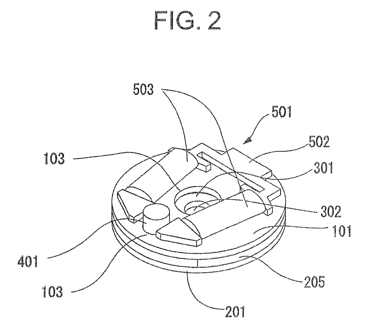
[0047]The light adjusting apparatus according to the first embodiment includes a substrate 101 in which, an optical aperture 102 is formed, a substrate 201 in which, an optical aperture 202 is formed, a light adjusting unit 301 in which an optical aperture 302 is formed, a stopper 204 which stops a movement of the light adjusting unit 301, a spacer 205 which is disposed between the substrate 101 and the substrate 201, and which is for creating a space in which, a blade (the light adjusting unit 301) is pivotably movable around a rotating shaft member 401, and an electromagnetic driving source 501 which turns the light adjusting unit 301.

[0048]In the first embodiment, an outer diameter φ of the rotating sh...

second embodiment

[0071]Next, a second embodiment of the present invention will be described below by using FIG. 5 through FIG. 8A, and FIG. 8B.

[0072]FIG. 5 is an exploded perspective view.

[0073]Moreover, same reference numerals are assigned to structural components which are equivalent to the structural components in the first embodiment.

[0074]A light adjusting apparatus according to the second embodiment of the present invention includes a substrate 101 in which, an optical aperture 102 is formed, a substrate 201 in which, an optical aperture 202 is formed, a light adjusting unit 301 in which, an optical aperture 302 is formed, a stopper 204 which stops a movement of the light adjusting unit 301, a spacer 205 which is disposed between the substrate 101 and the substrate 201, and which is for creating a space in which, a blade (the light adjusting unit 301) is pivotably movable around a rotating shaft member 401, and an electromagnetic driving source 501 which turns the light adjusting unit 301.

[007...


PUM


Abstract

A light adjusting apparatus according to the present invention includes a first substrate and a second substrate having an optical aperture, a rotating shaft member which has been rotatably installed with respect to the first substrate and the second substrate, a light adjusting unit which is joined to the rotating shaft member, and a driving unit which moves the light adjusting unit by driving to rotate the rotating shaft member. Light which passes through the optical aperture is adjusted by moving the light adjusting unit by rotating the rotating shaft member by the driving unit. The light adjusting unit has a notch, and the rotating shaft member and the light adjusting unit are joined at the notch.

Description

CROSS-REFERENCE TO RELATED APPLICATION[0001]The present application is based upon and claims the benefit of priority from the prior Japanese Patent Application No. 2010-152794 filed on Jul. 5, 2010; the entire contents of which are incorporated herein by reference,BACKGROUND OF THE INVENTION[0002]1. Field of the Invention[0003]The present invention relates to a light adjusting apparatus.[0004]2. Description of the Related Art[0005]In recent years, with improved high-quality performance of a portable equipment having an image pickup function, and a small-size optical apparatus such as a micro video scope, with regard to optical elements such as a lens, an aperture, there has been increasing demand for an application of a focusing lens, a variable aperture instead of a conventional fixed focusing lens and a fixed aperture stop, and further small-sizing (slimming) of such optical elements has been sought.[0006]For example, in Japanese Patent Application Laid-open Publication No. Hei 10...

Claims


Application Information

Patent Timeline
Patent Type & Authority Applications(United States)
IPC IPC(8): G02B7/04
CPCG02B26/02G02B5/005
Inventor OKITA, TATSUHIKO
Owner OLYMPUS CORP
Why Eureka
Try Eureka