Base station apparatus and method in mobile communication system

a mobile communication system and base station technology, applied in the field of mobile communication, can solve the problems of affecting the quality of the signal of the user apparatus residing in the cell edge, the inability to provide proper reception quality at all times, and the inability to provide proper signal quality at all times

Inactive Publication Date: 2012-01-05
NTT DOCOMO INC
View PDF8 Cites 37 Cited by
  • Summary
  • Abstract
  • Description
  • Claims
  • Application Information

AI Technical Summary

Benefits of technology

[0025]An object of the present invention is to reduce a fear that two or more communication apparatuses in which RTTs are different with each other use the same radio resource for retransmission respectively in a mobile communication system in which the synchronization type ARQ is performed and radio resources for retransmission are determined according to a predetermined hopping pattern.

Problems solved by technology

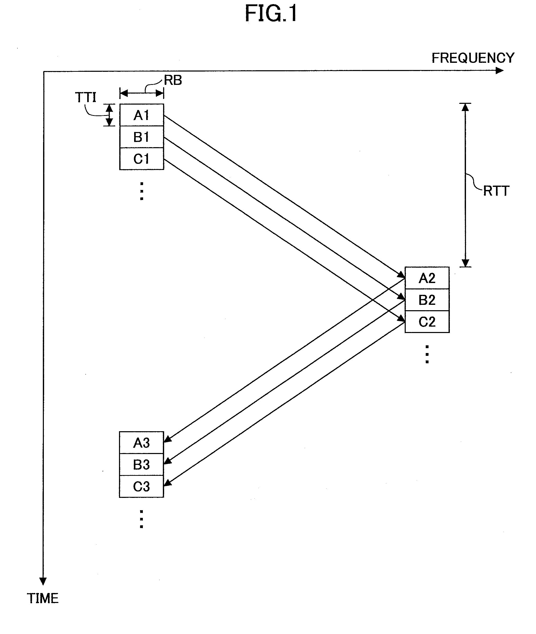
However, the signal of one subframe does not necessarily provide proper reception quality at all times. For example, quality of a signal from a user apparatus residing in a cell edge tends to become lower than quality of a signal from a user apparatus near a base station.

Method used


Image

  • Base station apparatus and method in mobile communication system
  • Base station apparatus and method in mobile communication system
  • Base station apparatus and method in mobile communication system

Examples


embodiment 1

1. Principle of Invention

[0057]FIG. 4 is a diagram for explaining the principle of the present invention. Similarly to FIGS. 1-3, the lateral axis indicates frequency, and the vertical axis indicates time. In FIG. 4, resource block numbers are shown in the lateral axis, and FIG. 4 indicates that 25 resource blocks in total are included in a system bandwidth (5 MHz, for example). The concrete numerical numbers such as the number of resource blocks and the system bandwidth and the like are merely examples, and any proper numbers may be used.

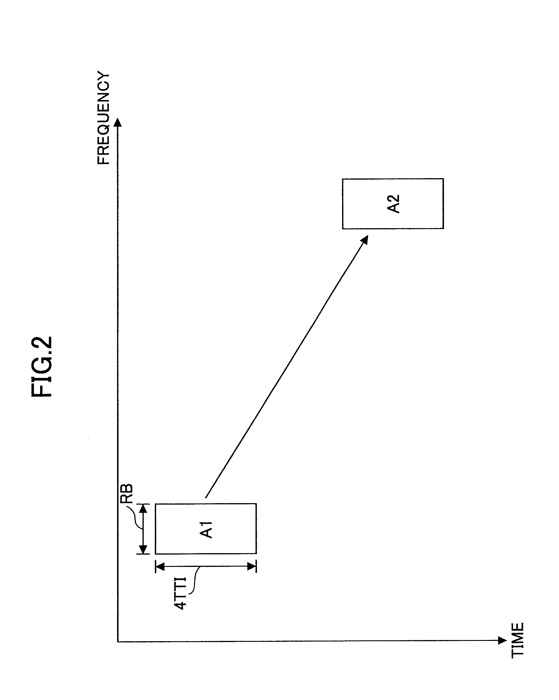
[0058]Similarly to the case of the example of FIG. 3, the RTT of a user apparatus that does not perform subframe bundling is 8 TTIs. The RTT of a user apparatus performing subframe bundling is 16 TTIs. FIG. 4 is similar to the case of FIG. 3 in the point that user apparatuses of different RTTs coexist. In the case of the example shown in FIG. 4, a retransmission radio resource of the user apparatus of RTT=8 TTIs is specified according to a first fr...


PUM


Abstract

A base station apparatus determines which mode of a subframe bundling mode (second mode) and a non-bundling mode (first mode) should be used by a user apparatus for communication, and reports a determination result. In the first mode, RTT period is a first period, and each of transmission and retransmission of the signal is performed every 1 TTI. In the second mode, RTT period is a second period that is longer than the first period, and each of transmission and retransmission of the signal is performed every plurality of TTIs. A radio resource to be used for retransmission is determined according to a first frequency hopping pattern in the first mode, and is determined according to a second frequency hopping pattern that is different from the first frequency hopping pattern in the second mode.

Description

TECHNICAL FIELD[0001]The present invention relates to a technical field of mobile communications. More particularly, the present invention relates to a base station apparatus and a method in a mobile communication system.BACKGROUND ART[0002]In this kind of technical field, successors to the so-called third-generation mobile communication system are being studied by 3GPP, a standardization group for the wideband code division multiple access (W-CDMA) scheme. In particular, not only Long Term Evolution (LTE) but also further succeeding mobile communication schemes such as the IMT-Advanced scheme are being discussed, as successors of the W-CDMA scheme, the high speed downlink packet access (HSDPA) scheme, and the high speed uplink packet access (HSUPA) scheme and the like.[0003]In a system such as LTE and the like, one or more resource blocks (RB) or resource units (RU) are allocated to a user apparatus (UE: User Equipment) both in downlink and uplink communications. Resource blocks ar...

Claims


Application Information

Patent Timeline
Patent Type & Authority Applications(United States)
IPC IPC(8): H04W72/04H04B1/713
CPCH04W28/06H04B1/713
Inventor ISHII, HIROYUKIKIYOSHIMA, KOHEIOKUBO, NAOTO
Owner NTT DOCOMO INC
Why Eureka
Try Eureka