Improved needle-free injectors

A technology of needle-free syringes and slide valves, applied in the direction of syringes, auto-injectors, hypodermic injection devices, etc., can solve the problems of reduced patient cooperation, high treatment costs, delayed treatment, etc.

Inactive Publication Date: 2013-10-23
ZOGENIX INC (US)
View PDF21 Cites 18 Cited by
  • Summary
  • Abstract
  • Description
  • Claims
  • Application Information

AI Technical Summary

Problems solved by technology

Inability to administer medication at home results in higher treatment costs, delays in processing, reduced patient compliance, reduced comfort, and possible exposure to nosocomial infections

Method used


Image

  • Improved needle-free injectors
  • Improved needle-free injectors
  • Improved needle-free injectors

Examples


example 1

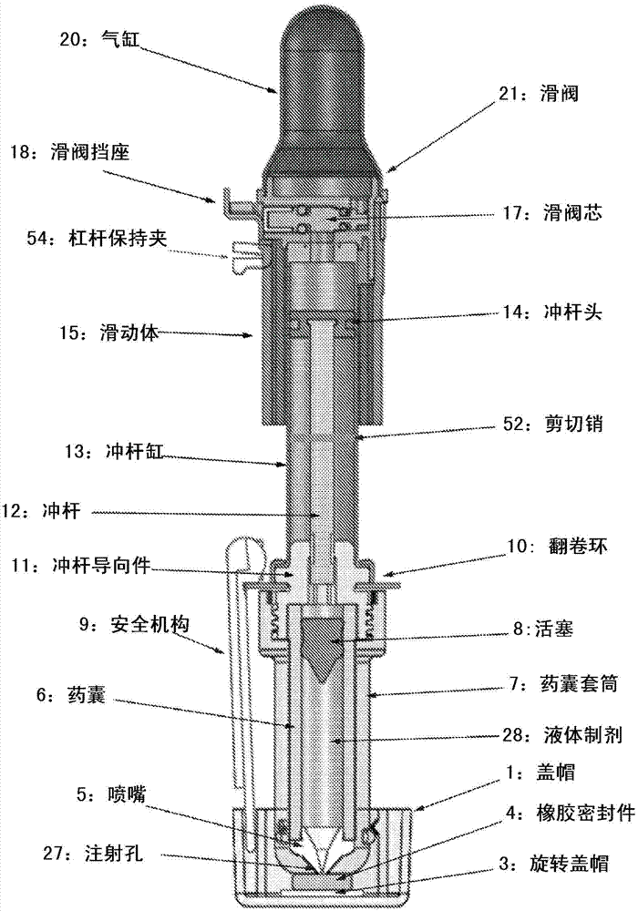
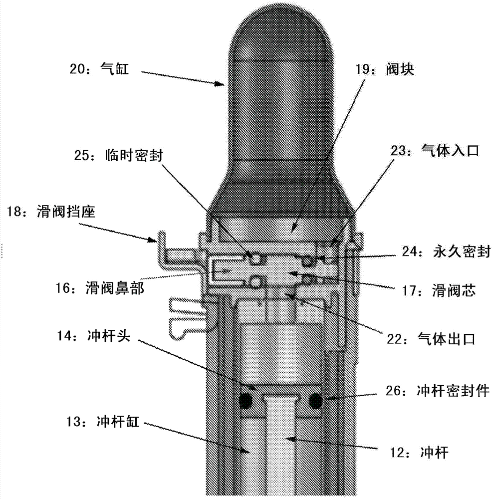
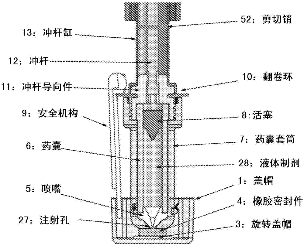
[0167] In Example 1, tests were carried out on laboratory prototypes, and important actuator characteristics of the system are shown in figure 1 and described above. The appearance of the prototype is shown in the Figure 11 a. To mimic the triggering effect of pressing the device against the skin, a simple collar 1150 is provided to release the spool 1117 . The preparation capsule 1106 is made of steel, and contains 1 ml of liquid preparation 1128, and includes an injection hole 1127 with a diameter of 0.41 mm. The air cylinder 1120 is pressurized to 60 bar via the gas source connection 1151 . Punch 1112 is held in place by shear pin 1152 . The operation of the prototype is shown in Figure 11 c. Collar 1150 slides upward, releasing spool 1117, allowing it to Figure 11 Move to the left as indicated by c. This allows pressurized gas to flow from the cylinder 1120, through the gas inlet 1123, through the area vacated by the spool 1117, and out the gas outlet 1122, wher...

example 2

[0169] In Example 2, experiments were performed with the laboratory setup described in Example 1, but using 0.5 ml glass formulation capsules, equivalent to those used in the '086 setup. The test results are shown in the Figure 13 , it can be seen that it is quite consistent with the results of the '086 device ( Figure 12b ), but with the same decrease in the piercing phase seen in Example 1.

example 3

[0171] In Example 3, experiments were carried out on a laboratory prototype (see Figure 14 a), which is designed to mimic Figure 4The twin cylinders shown in and described above. Two pressures are obtained by filling the cylinder central region 1435 with a first pressure P1 and then filling the cylinder peripheral region 1438 with a second, lower pressure P2. The plunger 1414 (note the plunger seal is omitted for clarity) is held in place with a detent 1453. The preparation capsule 1406 is made of steel, and contains 1 ml of liquid preparation 1428, and includes an injection hole 1427 with a diameter of 0.4 mm. The cylinder central area 1435 is filled to a pressure P1 of 200 MPa. The cylinder peripheral area 1438 is filled to a pressure P2 of 180 MPa. When the detent 1453 is pushed to such as Figure 14 On the right as shown in c, the plunger 1414 is released and accelerated through the impact gap 1443 by the force of the pressurized gas in the central area 1435 of the ...


PUM


Abstract

Improved needle free injectors comprising of a energy sources, triggering mechanisms, impact members, and drug delivery pistons are disclosed. In one preferred embodiment, the triggering mechanism comprises a spool which seals an energy source comprised of compressed gas and a component for releasing the spool to release the pressurized gas and urge a ram forward to force a drug containing formulation through a drug delivery orifice. The device may include a cap covering the orifice and safety mechanisms to prevent accidental delivery

Description

technical field [0001] The present invention relates to needle-free injectors, techniques to improve the reliability and manufacturability of needle-free injectors, and needle-free injectors capable of delivering increased doses. Background technique [0002] Many patients are injection opponents or suffer from injection phobia, or fear of self-administering injection-based medical injections. Many patients and / or health care workers have additional difficulties, including the inability or unwillingness to follow complicated instructions for use; the risk of needlestick injuries; and cross-infection. It can be said that there are many problems in ensuring the cooperation of treatment. In addition, there is a problem that patients may need to be trained to self-administer injections, but some cases indicate that there are few injections that patients can self-administer. In addition, needles and syringes often need to be filled and, for certain prescriptions, dry medication...

Claims


Application Information

Patent Timeline
Patent Type & Authority Applications(China)
IPC IPC(8): A61M5/30
CPCA61M5/2053A61M5/30A61M2005/3104A61M2005/2073
Inventor B·M·博伊S·J·法J·A·舒斯特A·弗赖伊A·波科克B·迈尔斯C·赫尔斯顿J·丹特瑞
Owner ZOGENIX INC (US)
Why Eureka
Try Eureka