Medical imaging inspection device

An inspection device, medical imaging technology, applied in medical science, measurement device, lighting device, etc., can solve problems such as patient health damage, reduce patient response ability, etc., to achieve the effect of noise reduction

Inactive Publication Date: 2004-12-01
SIEMENS AG
View PDF0 Cites 18 Cited by
  • Summary
  • Abstract
  • Description
  • Claims
  • Application Information

AI Technical Summary

Problems solved by technology

Such sedatives reduce the responsiveness of some patients for a long time after the test and often leave patients feeling unwell or completely compromised

Method used


Image

  • Medical imaging inspection device
  • Medical imaging inspection device
  • Medical imaging inspection device

Examples


Embodiment Construction

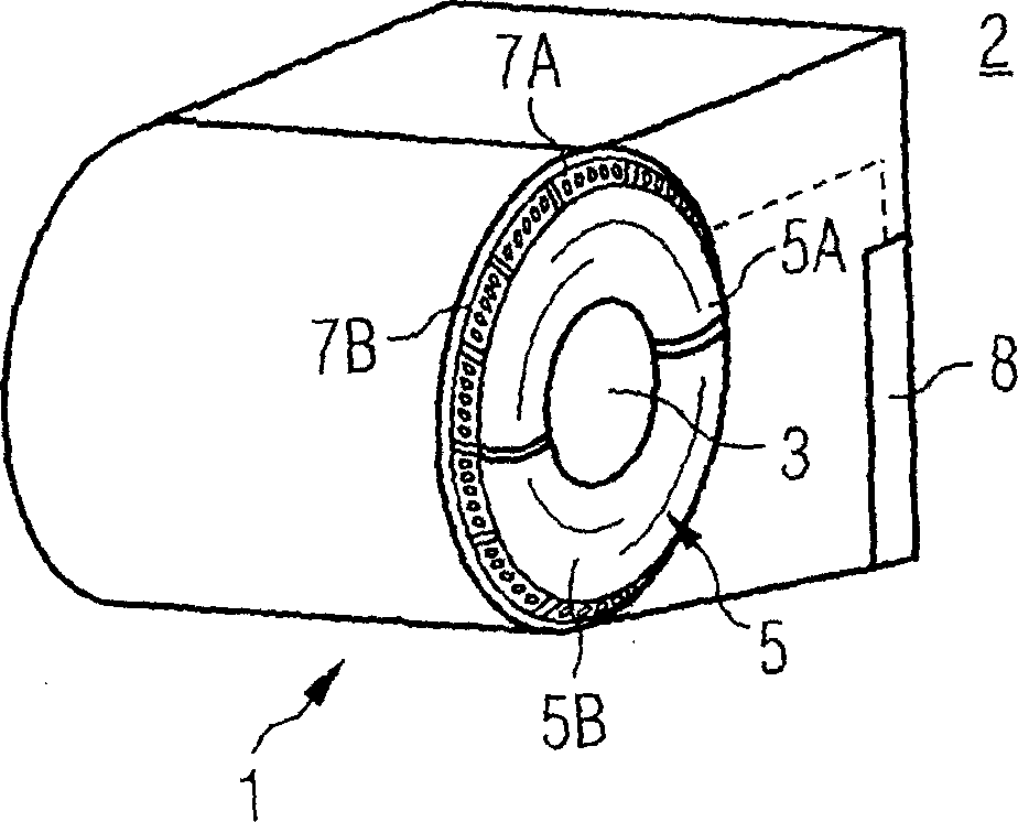
[0030] figure 1A hollow cylinder 1 that is commonly used in medical imaging examination devices 2 is shown. The hollow cylinder can contain, for example, the base magnet of a magnetic resonance tomograph, the radiation detector of a computer tomograph or a positron emission tomograph. The hollow cylinder 1 is the main part constituting the external shape of the medical imaging inspection device. For example, the patient can be sent into the hole 3 by means of an examination table not shown in the figure. The hole is composed of an upper front wall part 5A and a lower front wall part 5B. The wall parts are each made of a translucent material. This separation makes loading, unloading and transporting of the front wall 5 easier. The front wall 5 has an annular cross-sectional shape and is curved outwards away from the hollow cylinder, for example in a central radial region. A plurality of LED modules 7A, 7B are located at the outer edge of the front wall, these LED modules be...


PUM


Abstract

A medical imaging examination apparatus has a front wall with an opening to a cylindrical examination area into which a patient to be examined can be moved, and has an illumination arrangement for the illumination of the front wall over a large surface. The illumination of the front wall reduces feelings of fear on the part of a patient, and thus simplifies conducting examinations using the examination apparatus.

Description

technical field [0001] The invention relates to an examination device for medical imaging with a front wall having an opening into a cylindrical examination area into which a patient to be examined can be introduced. Background technique [0002] In order to examine a patient with the aid of a medical imaging device, the region of the patient to be examined is brought into an examination field in the medical imaging device. For example, in most magnetic resonance tomography, computed tomography and positron emission tomography systems the examination region is designed as a cylinder. Since the examination area has, for example, a diameter slightly larger than the average shoulder width (approximately 60 cm), the entire patient can be inserted into the examination area. The examination region is surrounded by elements for imaging which together form a housing which is largely filled. [0003] When considering the use of large examination devices, the mere sight of sending a...

Claims


Application Information

Patent Timeline
Patent Type & Authority Applications(China)
IPC IPC(8): A61B5/055A61B6/04A61M21/00A61N5/06G01R33/28G01R33/385
CPCA61M2021/0044A61N2005/0652A61N2005/0663A61M21/00G01R33/28G01R33/3854A61B6/04A61B5/0555A61B5/055
Inventor 克里斯托夫·博宁格彼得·迪斯特勒何哈德·赫尔姆赖克
Owner SIEMENS AG
Why Eureka
Try Eureka