Wireless network

a wireless network and wireless technology, applied in the field of wireless networks, can solve problems such as interference, interference, and disruption of communication, and achieve the effects of reducing interference risk, maintaining or increasing throughpu

Active Publication Date: 2012-01-05
LUMENRADIO
View PDF3 Cites 9 Cited by
  • Summary
  • Abstract
  • Description
  • Claims
  • Application Information

AI Technical Summary

Benefits of technology

[0009]An object with the present invention is to provide a wireless network that reduces the risk of interference from other wireless networks with a maintained or increased throughput compared to prior art networks.
[0011]An advantage with the present invention is that interference from wireless networks present in the coverage area of the wireless network may be reduced by selecting local and common communication parameters.
[0012]Another advantage with the present invention is that the coverage area of the wireless network may be expanded compared to prior art networks.

Problems solved by technology

The task to create networks covering large areas and spanning over vast distances, in environments where many wireless networks are simultaneously operating, have always been a challenge.
In addition to the challenge to cover large areas, interference from other wireless devices will vary from one location to another.
Furthermore, interference will vary over time due to the fact that some wireless networks are used more at certain hours of the day, and others new wireless networks may also be installed.
If a network is expanded to cover a large area where a number of WiFi networks and other wireless networks are operating, the problem with interference arises.
The use of the same communication parameters, such as frequency, in the different networks may result in disrupted communication.
It should be noted that not only the expanded large area network may be disrupted due to the interference between the networks, but most certainly the local WiFi networks will be disrupted resulting in a lower quality of service for the WiFi hotspots.
The sum of all frequencies used within the entire building, which may be considered to be a large area network, results in a loss of available frequencies to use.
This may result in communication drop outs.

Method used


Image

  • Wireless network
  • Wireless network
  • Wireless network

Examples


example

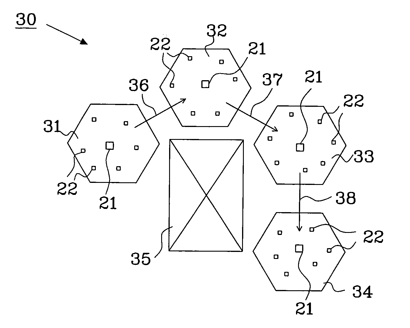
[0051]Two subnets, subnet 31 and subnet 32, shall communicate.

[0052]Each neighboring subnet uses a unique set of communication parameters for internal subnet communication. Subnet 31 uses communication parameters A, B, C and subnet 32 uses communication parameter C, D, E. The communication between subnet 31 and 32 is performed using the union of both which is parameter C, i.e. the common communication parameter. In this example, communication parameters A-E may be exemplified as five different frequency ranges, wherein the common frequency range “C” illustrate a common communication channel in the frequency domain being shared by subnet 31 and 32. The frequency ranges “A” and “B” illustrate two communication channels in the frequency domain available for internal communication in subnet 31, and the frequency ranges “D” and “E” illustrate two communication channels in the frequency domain available for internal communication in subnet 32.

[0053]A subnet that is a part of a wireless ne...


PUM


Abstract

The present invention relates to a wireless network 30; 60 including at least two subnets 31-34; 61-63. Each subnet comprises a plurality of units 21, 22 configured to wirelessly communicate with each other. The wireless network is configured to select a local set of communication parameters CP1, CP3 for internal communication within each subnet in such a way that internal communication within neighbouring subnets uses different local sets of communication parameters to prevent interference between neighboring subnets, and to select at least one common set of communication parameters CP2 for each subnet to be used when communicating between subnets in the wireless network 30; 60. The invention also relates to a method for adapting a wireless network, a method for forming a wireless network and a communication unit.

Description

TECHNICAL FIELD[0001]The present invention relates to a wireless network having a plurality of subnets, especially configured to adapt to a wireless environment.BACKGROUND[0002]The task to create networks covering large areas and spanning over vast distances, in environments where many wireless networks are simultaneously operating, have always been a challenge. Such environments are typically found in urban and industrial areas. In addition to the challenge to cover large areas, interference from other wireless devices will vary from one location to another. For instance, WiFi may be extensively used at one location in the network and thereby occupying a large portion of the available frequencies, and different frequencies may be occupied elsewhere in the network.[0003]Furthermore, interference will vary over time due to the fact that some wireless networks are used more at certain hours of the day, and others new wireless networks may also be installed. An example of this is WiFi ...

Claims


Application Information

Patent Timeline
Patent Type & Authority Applications(United States)
IPC IPC(8): H04W72/04
CPCH04W84/18H04W16/14
Inventor NORLEN, NICLASPER, HULTHEN
Owner LUMENRADIO
Why Eureka
Try Eureka