Technology for fault allocation in passive optical networks (PON)

a technology of fault allocation and optical network, applied in the field of fault allocation in passive optical network, can solve the problems of difficult detection and sorting of optical signals received from onts, olt will be unable to recognize why the onts have stopped responding/transmitting, and the fault allocation in pon, so as to achieve simple, passive and cost-effective

Active Publication Date: 2012-01-05
ECE TELECOM LTD
View PDF35 Cites 20 Cited by
  • Summary
  • Abstract
  • Description
  • Claims
  • Application Information

AI Technical Summary

Benefits of technology

[0005]It is the object of the present invention to propose a simple, passiv

Problems solved by technology

A problem of fault allocation in PON stems from the very nature of passive optical networks.
Owing to that, if an optical fiber, terminating with a specific ONT, fails or degrades—OLT will be unable to recognize why the ONTs have stopped responding/transmitting.
Since upstream signals from ONTs are mixed with one another in the common optical fiber leading to OLT, and since the splitters always introduce high attenuation to the OTDR signal (normal attenuation number is 40 dB), the optical signals received from the ONTs are quite difficult for detecting and sorting properly.
Any increase of power or duration of probe sig

Method used


Image

  • Technology for fault allocation in passive optical networks (PON)
  • Technology for fault allocation in passive optical networks (PON)
  • Technology for fault allocation in passive optical networks (PON)

Examples


Embodiment Construction

[0036]The invention will be further described with reference to the following non-limiting examples, in which:

[0037]FIG. 1 (prior art) illustrates an example of a conventional diagnostic technique in a PON network.

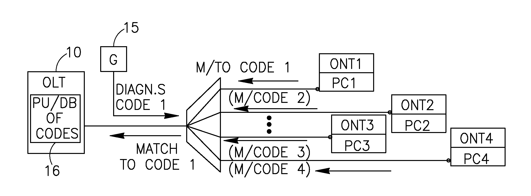
[0038]FIG. 2 schematically shows one example of the proposed arrangement of a system with diagnostic points in the PON network, provided with the proposed passive diagnostic tools.

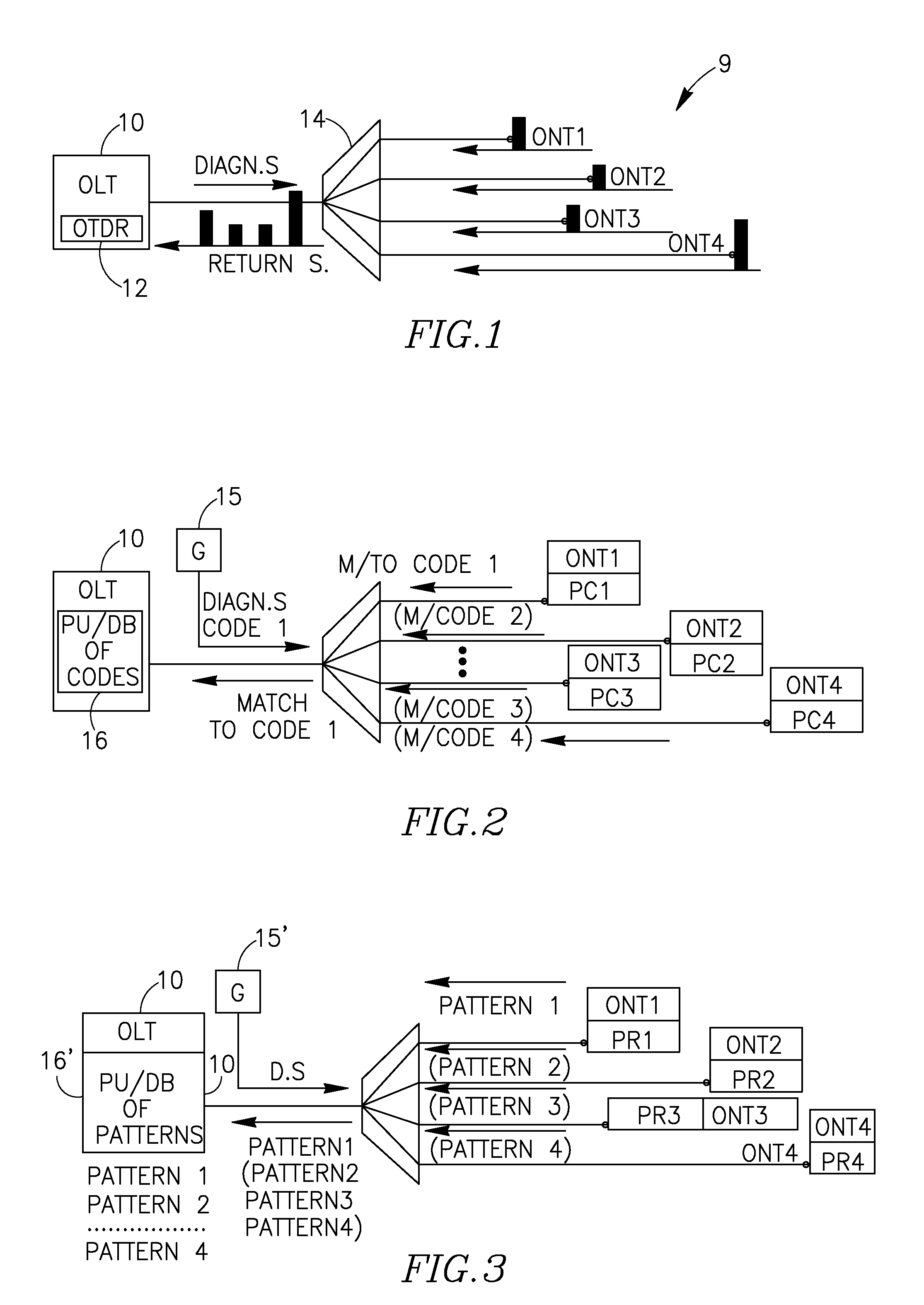
[0039]FIG. 3 schematically shows another example of the proposed arrangement of a system with diagnostic points in the PON network, provided with the passive diagnostic tools being pattern / image reflecting pixel-based optical devices.

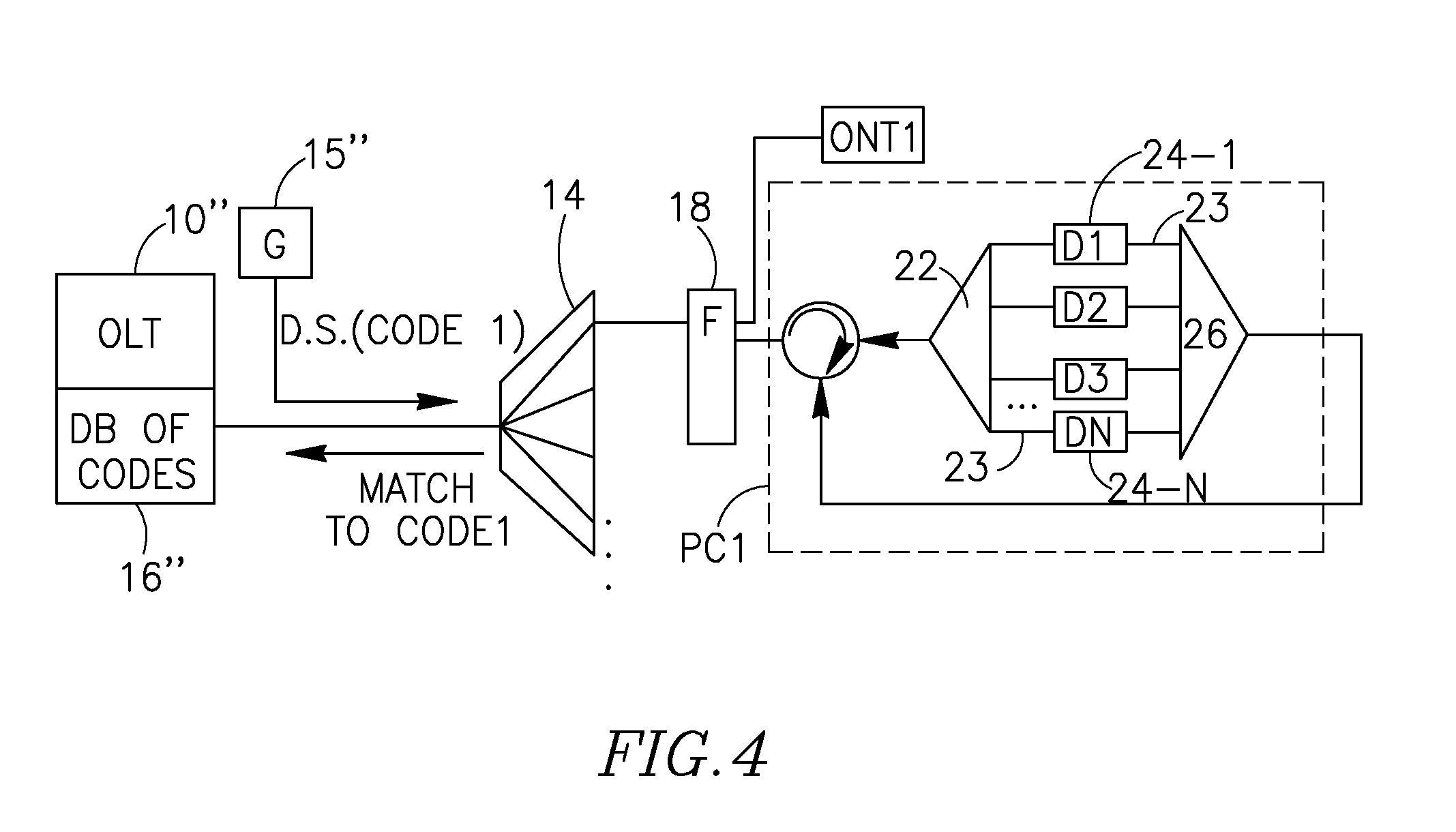
[0040]FIG. 4 schematically illustrates one example of the proposed optical correlator, built using optical delay elements.

DETAILED DESCRIPTION OF THE INVENTION

[0041]FIG. 1 shows a PON network with its OLT 10 incorporating an OTDR unit 12. The OTDR unit, via a splitter 14, transmits an optical diagnostic / probe signal towards a group of ONTs of the PON. The splitter (a...


PUM


Abstract

A method for allocating faults in a passive optical network (PON) by placing a number of passive unique optical correlators in a number of respective diagnostic points of the PON, each of the passive unique optical correlators being responsive to an optical diagnostic signal by returning a predetermined unique matching signal; by further transmitting the diagnostic optical signal in the PON towards the diagnostic points to receive upstream response signals from the correlators. Upon detecting presence or absence, in the received response signals, of a predetermined unique matching signal expected from a specific optical correlator, judging about a fault in proximity of the respective specific diagnostic point.

Description

FIELD OF THE INVENTION[0001]The present invention relates to a technique of allocating faults in passive optical networks (PON) such as GPON, BPON, EPON, GEPON, WDM-PON.BACKGROUND OF THE INVENTION[0002]A problem of fault allocation in PON stems from the very nature of passive optical networks. Namely, at the PON physical layer, any information transmitted from one (central) Optical Line Termination (OLT) via an optical splitter, will be automatically shared between all fibers outgoing the splitter and terminating with Optical Network Terminations (ONTs). Similarly, information transmitted from any of the ONTs cannot be recognized by OLT as belonging to a specific ONT. This fact is due to the physical characteristics of the PON. Owing to that, if an optical fiber, terminating with a specific ONT, fails or degrades—OLT will be unable to recognize why the ONTs have stopped responding / transmitting. OTDR testing systems are based on analyzing power of returning optical signals, and on th...

Claims


Application Information

Patent Timeline
IPC IPC(8): H04B10/08H04B10/077H04B10/272
CPCH04B10/0771H04Q2011/0083H04Q11/0067H04B10/272H04J14/0272H04J14/0282
Inventor MELAMED, AMITAY
Owner ECE TELECOM LTD
Why Eureka
Try Eureka