Temperature Compensated Current Source

a current source and temperature compensation technology, applied in pulse generators, pulse techniques, instruments, etc., can solve the problems of inability to completely eliminate the problem of temperature influence on the components used to generate current signals, inability to accurately reproduce current signals in ic chips,

Active Publication Date: 2012-01-12
TEXAS INSTR INC
View PDF5 Cites 17 Cited by
  • Summary
  • Abstract
  • Description
  • Claims
  • Application Information

AI Technical Summary

Problems solved by technology

One problem that typically affects the accuracy of current signals in IC chips is the impact temperature has on components used to generate the current signals.
Since avoiding temperature fluctuations altogether is typically no

Method used


Image

  • Temperature Compensated Current Source
  • Temperature Compensated Current Source
  • Temperature Compensated Current Source

Examples


Embodiment Construction

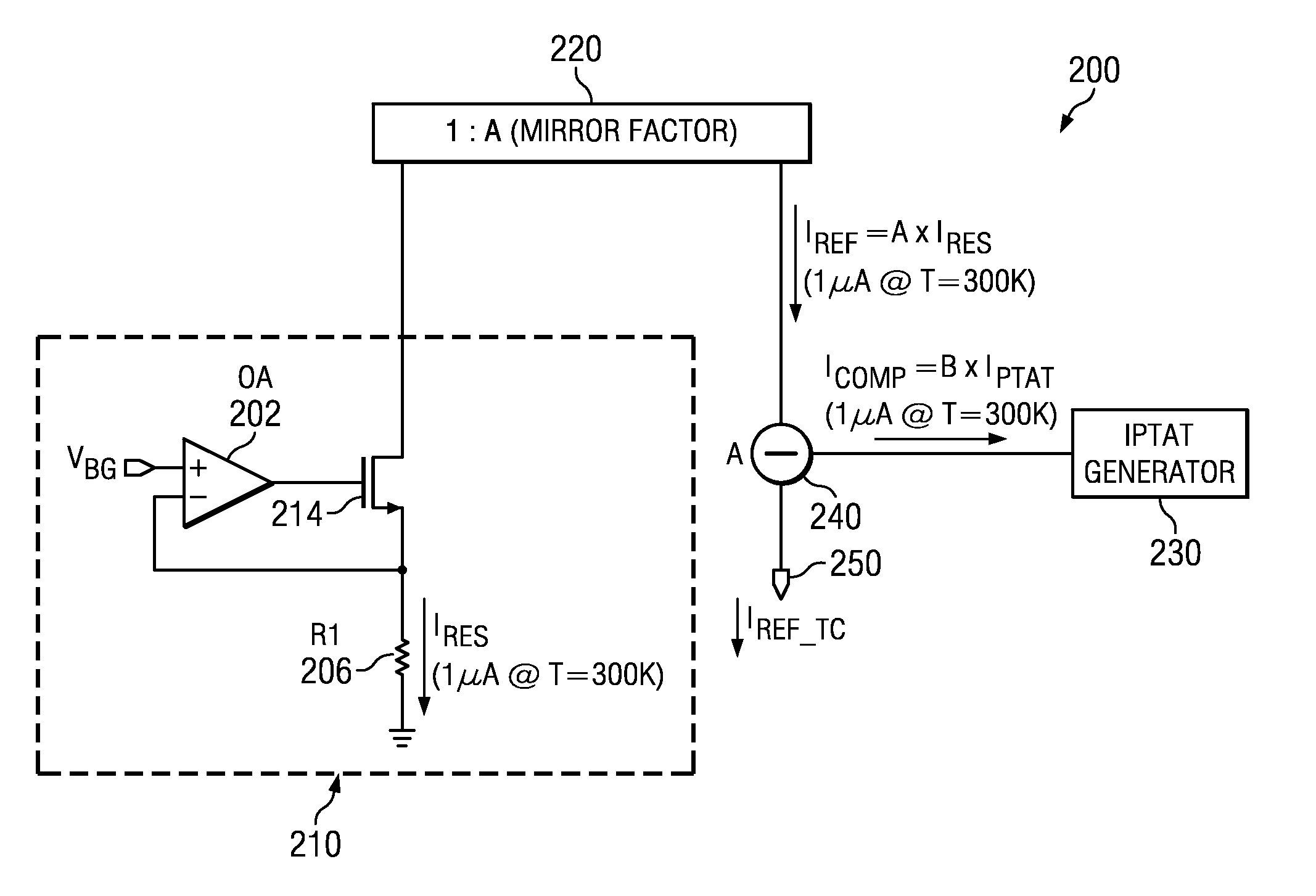
[0014]An embodiment of the present invention provides a temperature compensated current source using an impedance based reference current and a compensation current that is proportional to absolute temperature.

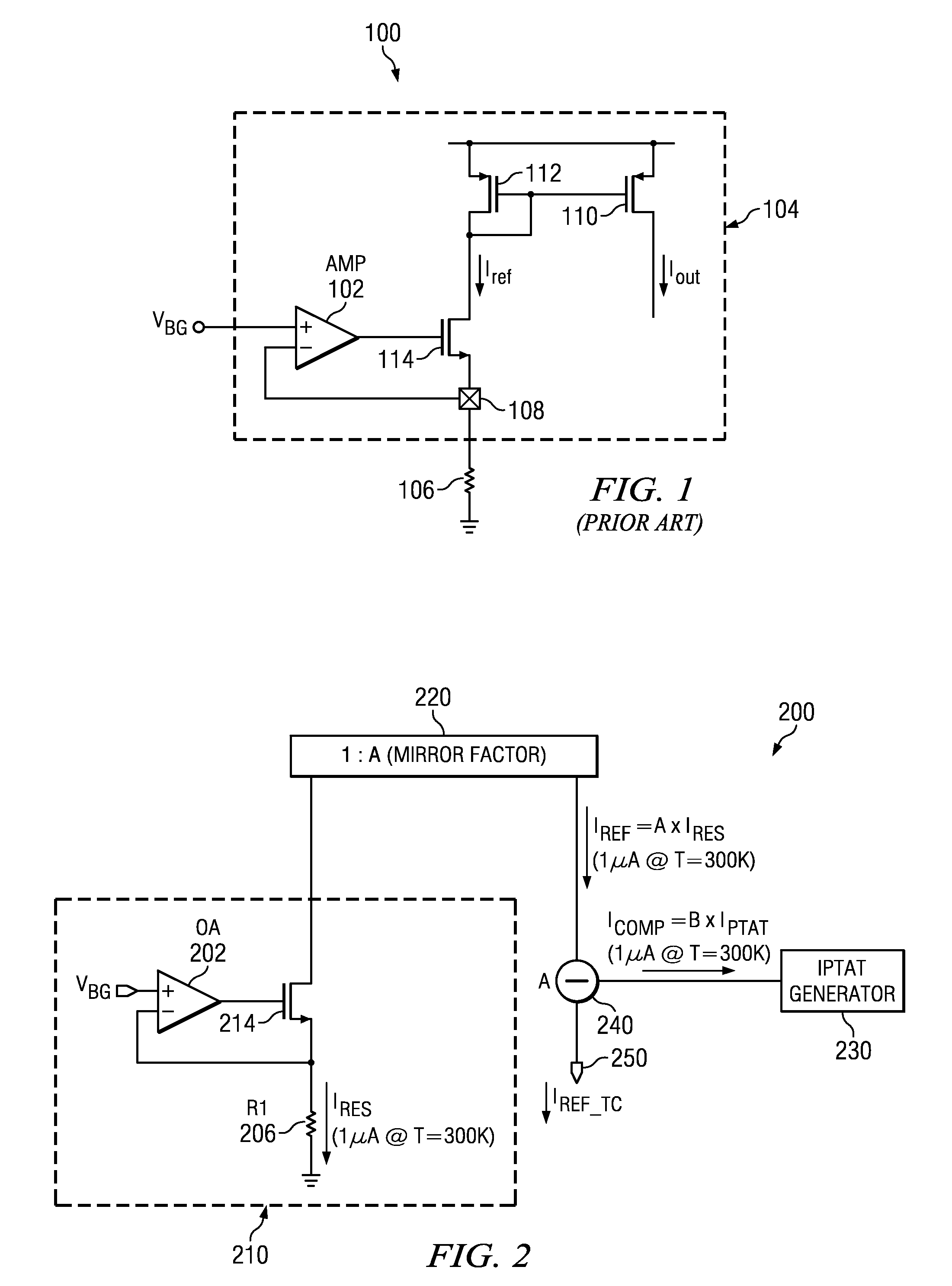
[0015]In order to better understand the principles disclosed herein, a conventional current source will be described briefly. FIG. 1 illustrates an embodiment of a conventional current source circuit 100. Circuit 100 may be used for generating an output current that may be used by various components in an integrated circuit chip, for example, as a reference signal for circuit biasing.

[0016]Current source 100 includes a differential amplifier 102 within an output current circuit 104. In addition, circuit 100 includes a resistive element 106, coupled to the output current circuit 104 via a bond pad 108. The output current circuit 104 includes first and second mirror transistors 110, 112, having their gates coupled together, and driven by a third transistor 114. The third transis...


PUM


Abstract

A temperature compensated current source forms an uncompensated source current that is proportional to a reference voltage applied to an impedance, wherein the impedance varies with temperature. A temperature compensation current is formed that is proportional to absolute temperature (IPTAT). The uncompensated source current and the temperature compensation current is combined to form a temperature compensated source current and provided as an output of the current source.

Description

CLAIM OF PRIORITY UNDER 35 U.S.C. 119(a)[0001]The present application claims priority to and incorporates by reference European Patent Application number, EP 10290378.8 (attorney docket TI-69148 EP-PS) filed Jul. 8, 2010, entitled “Temperature Compensated Current Source.”FIELD OF THE INVENTION[0002]This invention generally relates to semiconductor devices, and in particular devices and circuits for providing a constant value current source with temperature compensation.BACKGROUND OF THE INVENTION[0003]In integrated circuit (IC) chip design, components and circuitry formed therein are typically operated using a variety of signals, including reference signals. Certain components operate based on voltage signals, while other components are designed to function based on current signals. As the complexity of integrated circuits continues to increase, the accuracy of such voltage and current reference signals becomes increasing important. One problem that typically affects the accuracy of...

Claims


Application Information

Patent Timeline
IPC IPC(8): H01L37/00
CPCG05F3/242G05F1/561
Inventor CUSINATO, PAOLO GIOVANNI
Owner TEXAS INSTR INC
Why Eureka
Try Eureka