Thin film magnetic head, head gimbals assembly, head arm assembly and magnetic disk device

a thin film magnetic head and head arm technology, applied in the field of thin film magnetic head, head arm assembly and magnetic disk device, can solve the problems of abrasion of the thin film magnetic head itself, insufficient control, abnormal signal generation, etc., and achieve high density recording and high precision.

Active Publication Date: 2012-01-12
TDK CORPARATION
View PDF1 Cites 19 Cited by
  • Summary
  • Abstract
  • Description
  • Claims
  • Application Information

AI Technical Summary

Benefits of technology

[0014]In the thin film magnetic head, the head gimbals assembly, the head arm assembly, and the magnetic disk device in the embodiments of the invention, the magnetic read head section and the magnetic write head section are each provided with a pair of heat generation means and temperature detection means. Such a configuration allows the magnetic read head section and the magnetic write head section to separately adjust the power application to the heat generation means in accordance with the temperature detected by their own temperature detection means. This accordingly enables to optimize the protrusion amount separately in the magnetic read head section and the magnetic write head section, thereby being able to control the magnetic spacing to be very small with a high precision between the ABS of the thin film magnetic head and the surface of the magnetic disk. This is considered very advantageous in terms of keeping up with the high density recording.

Problems solved by technology

However, this attempt has failed in not providing enough control, and as a result, the thin film magnetic head comes in contact with very small protrusions or others on the surface of the magnetic disk.
This thus causes problems including generation of abnormal signals due to heat generation, and abrasion of the thin film magnetic head itself, for example.
With the thin film magnetic head in Japanese Unexamined Patent Publication No. 2003-168274, however, there is a problem of difficulty in controlling an extremely small magnetic spacing with a high precision through control over the power application to the heating element.
Similarly, with the thin film magnetic head in Japanese Unexamined Patent Publication No. 2003-272335, due to the configuration that the heating elements are so provided as to sandwich therebetween the magnetic conversion element along the rotation direction of the magnetic disk, the displacement in response to any change of power application may not be enough in the direction orthogonal to the ABS.
As a result, the heat generation of the heating elements may possibly increase also the temperature of the magnetic conversion element.
Also similarly, with the magnetic disk device in the Specification of U.S. Pat. No. 5,991,113, the distance is large between the heating element and the magnetic conversion element, and this thus may result in a large time lag until the amount of protrusion shows a change after the change of power application.
Also similarly, with the magnetic head slider in Japanese Unexamined Patent Publication No. 2008-165950 and that in Japanese Unexamined Patent Publication No. 2007-280502, a certain degree of control may be indeed possible over the distance between the read element and the surface of the magnetic disk, but a sufficient degree of control may be difficult over the distance between a write element and the surface of the magnetic disk.

Method used


Image

  • Thin film magnetic head, head gimbals assembly, head arm assembly and magnetic disk device
  • Thin film magnetic head, head gimbals assembly, head arm assembly and magnetic disk device
  • Thin film magnetic head, head gimbals assembly, head arm assembly and magnetic disk device

Examples


Embodiment Construction

[0020]In the below, an embodiment of the invention is described in detail by referring to the accompanying drawings.

[Configuration of Magnetic Disk Device]

[0021]First of all, by referring to FIGS. 1 and 2, the configuration of a magnetic disk device of the embodiment of the invention is described below.

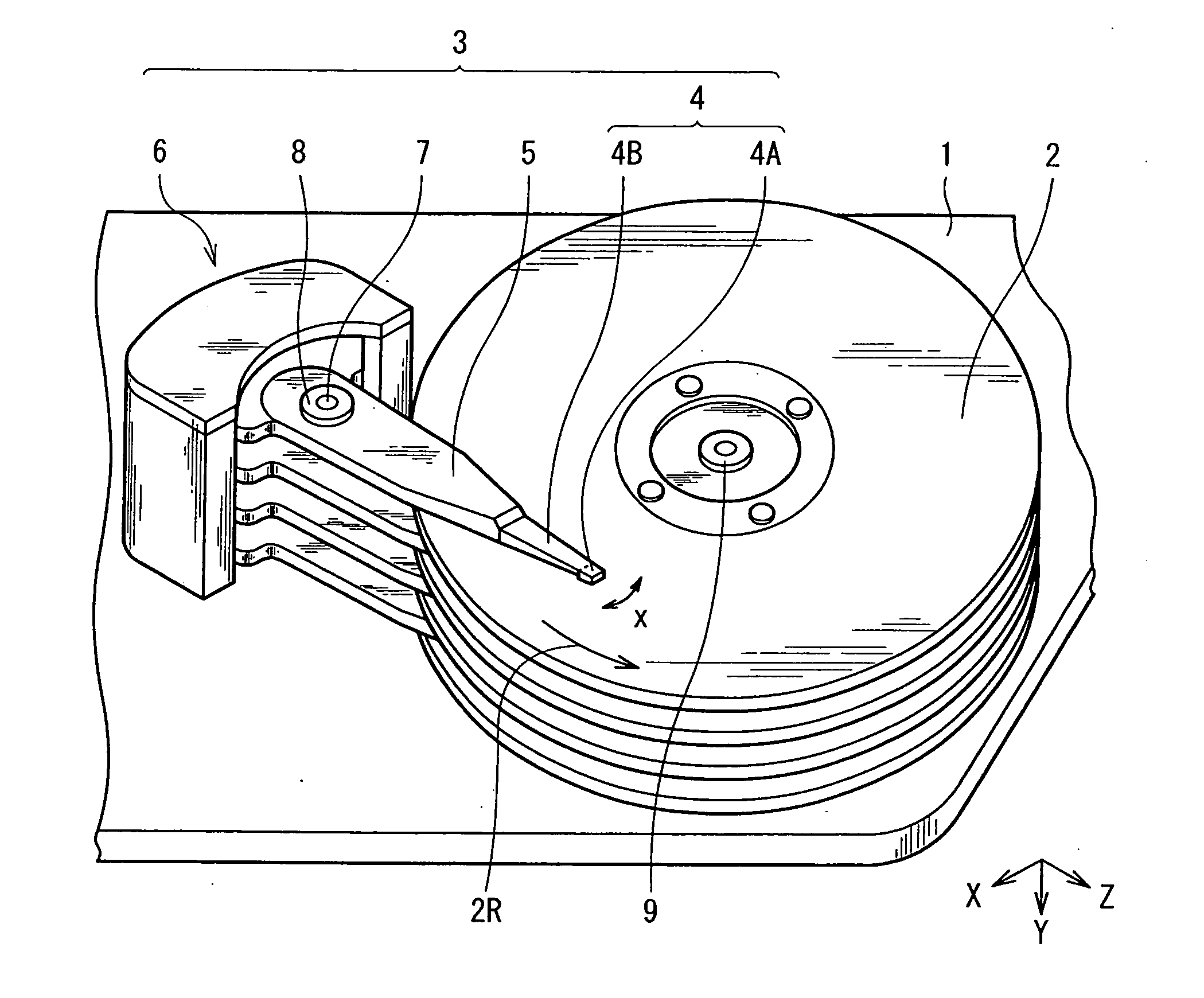
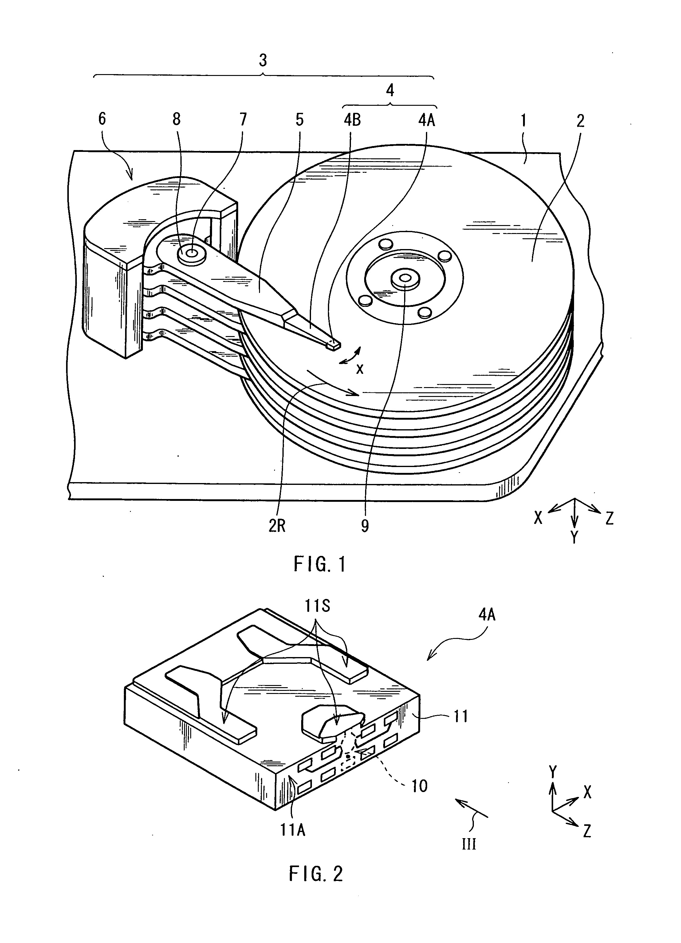
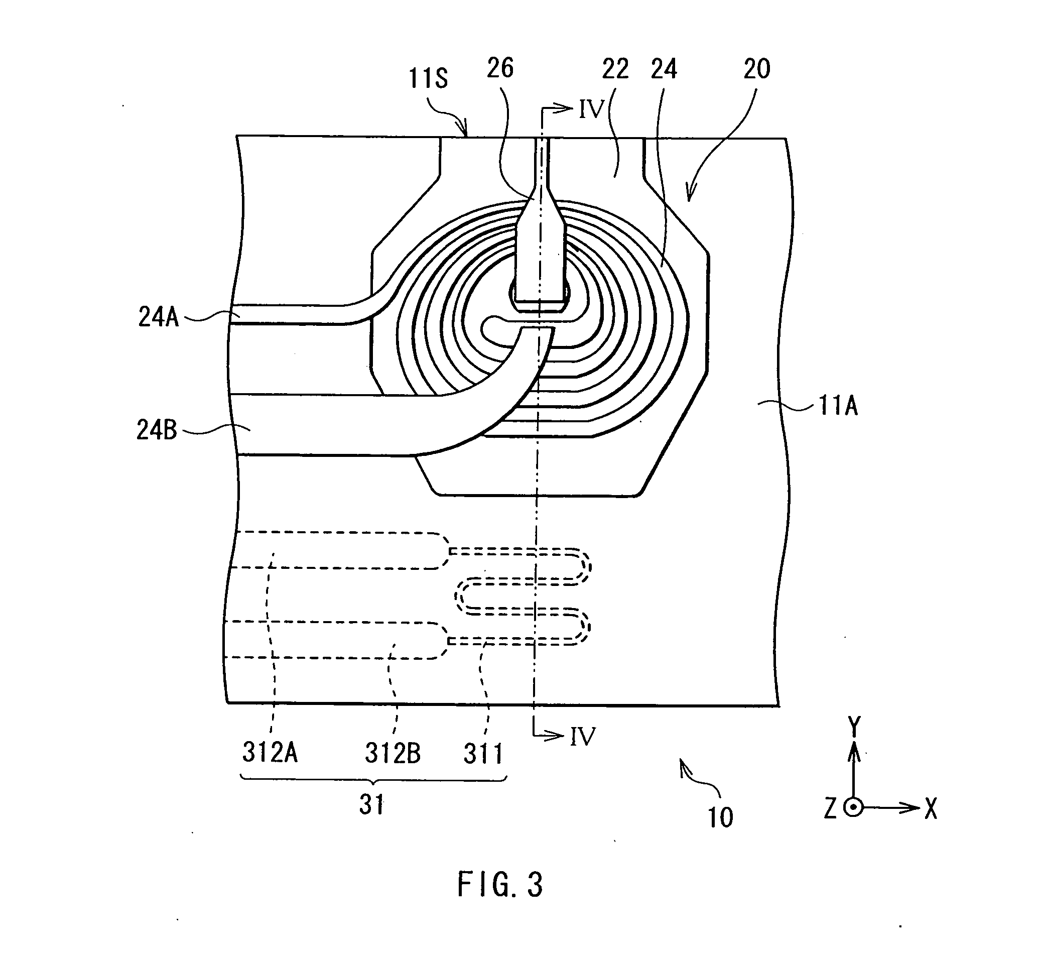
[0022]FIG. 1 is a perspective view of the magnetic disk device of the embodiment, showing the internal configuration thereof. This magnetic disk device operates in a CSS (Contact-Start-Stop) mode as a driving mode, and is configured to include a magnetic disk 2 and a head arm assembly (HAA; Head Arm Assembly) 3 inside of a chassis 1, for example. The magnetic disk 2 serves as a magnetic recording medium for recording of information, and the HAA 3 is provided for recording of information onto the magnetic disk 2, and for reproduction of the information. The HAA 3 is configured to include a head gimbals assembly (HGA; Head Gimbals Assembly) 4, an arm 5 for supporting the base portion of...


PUM

PropertyMeasurementUnit
thicknessaaaaaaaaaa
thicknessaaaaaaaaaa
thicknessaaaaaaaaaa

Abstract

This thin film magnetic head has a magnetic read head and a magnetic write head each having respective end surfaces exposed to an ABS. The magnetic read head includes a magnetic reader including an end surface exposed to the ABS, first heat generator disposed on an opposite side of the magnetic reader from the ABS, and first temperature detector disposed closer to the ABS than the first heat generator is. The magnetic write head includes a magnetic pole having an end surface exposed to the ABS, second heat generator, and second temperature detector disposed closer to the ABS than the second heat generator is. The first heat generator and the first temperature detector adjust the protrusion of the magnetic read head, and the second heat generator and the second temperature detector adjust the protrusion of the magnetic write head.

Description

BACKGROUND OF THE INVENTION[0001]1. Field of the Invention[0002]The present invention relates to a thin film magnetic head incorporating both a magnetic read head section and a magnetic write head section, a head gimbals assembly, a head arm assembly, and a magnetic disk device.[0003]2. Description of the Related Art[0004]For recording and reading of magnetic information (hereinafter, simply referred to as information), a magnetic disk device has been used. The magnetic disk device is configured to include, in a chassis, a magnetic disk and a thin film magnetic head, for example. The magnetic disk is the one for storage of information, and the thin film magnetic head is for recording of information onto the magnetic disk, and for reproduction of the information recorded on the magnetic disk. The magnetic disk is supported by the rotation shaft of a spindle motor, and is so configured as to rotate about the shaft. The spindle motor is being fixed to the chassis. On the other hand, th...

Claims


Application Information

Patent Timeline
Patent Type & Authority Applications(United States)
IPC IPC(8): G11B5/02
CPCB82Y25/00G01R33/093G11B5/607G11B5/3136G11B5/3967G11B5/3106G11B2005/3996G11B5/314G11B5/3163
Inventor NISHIOKA, YASUSHINAKATOGAWA, KAZUMIKANAYA, TAKAYASU
Owner TDK CORPARATION
Why Eureka
Try Eureka