Surgical instrument

a surgical instrument and cleaning technology, applied in the field of surgical instruments, can solve the problems of inability to transfer the sliding part by single-handed operation from a working position into a cleaning position, the cleaning purpose of known surgical instruments is to some extent to be dismantled, and the cleaning is not easy to achieve. , the effect of simple construction

Active Publication Date: 2012-01-12
KARL LEIBINGER MEDIZINTECHNIK GMBH CO KG
View PDF6 Cites 21 Cited by
  • Summary
  • Abstract
  • Description
  • Claims
  • Application Information

AI Technical Summary

Benefits of technology

[0010]The locking means are quite particularly preferably constructed such that on actuation they are constructed displacing a stop position for the pivotable grip part, mechanically coupled (operatively connected) with the sliding part. Here, the different stop positions on the one hand define the working position, in which the sliding part is guided as to be non-rotatable longitudinally displaceably on the shaft part and on the other hand the cleaning position, in which the sliding part is freed from the guide and is pivotable about the rotation axis relative to the shaft. In other words, the locking means makes possible, after actuation, a further pivoting of the grip part compared with the working position, and hence a further longitudinal displacement of the sliding part relative to the shaft (preferably toward the rear), so that the sliding part comes free from the guide and is then pivotable in the cleaning position about the rotation axis.
[0011]An embodiment of the surgical instrument is quite particularly preferred, in which the different stop positions for the pivotable grip part are formed by different diameter sections of a locking bolt of the locking means, wherein the diameter sections differ as regards the size of their diameter. Preferably, the diameter section defining the cleaning position has a smaller diameter than the diameter section defining the working position, in order to thereby make possible a further pivoting of the pivotable grip part and hence a further longitudinal displacement of the sliding part relative to the shaft part.
[0013]The provision of locking means with a locking bolt having at least two, in particular axially adjacent diameter sections makes possible, in combination with the alignment according to the invention of the rotation axis for the sliding part, a good single-handed operability of the surgical instrument.
[0014]An embodiment of the surgical instrument is quite particularly preferred in which the pivotable grip part is spring-loaded against the locking bolt, having at least two diameter sections, of the locking means, i.e. in the direction of its stop position, so that the pivotable grip part and hence the sliding part, after actuation of the locking bolt, is immediately automatically displaced into the cleaning position, in which the sliding part is pivotable about the rotation axis relative to the shaft. Such an embodiment is optimal with regard to ensuring single-handed operability.
[0022]In particular, in a realized embodiment of the receiving slot as previously described, it is preferred if the carrier section, in particular in the shape of a bar or rod, is supported at both end sides, by the carrier section being received between two side sections of the sliding shaft. The carrier section is preferably constructed in one piece with the two side sections of the sliding shaft, wherein it is alternatively able to be realized to construct the carrier section as a separate component and to secure it between the side sections of the sliding shaft, for example by welding or accommodation in two fixing openings. In an alternative embodiment, the carrier section is only fixed on one side and has a free end. In such an embodiment, the carrier section can simply be guided out from the receiving slot of the jaw part by lateral pivoting of the sliding part. Such an embodiment is suitable in particular for comparatively large surgical instruments, in which the carrier section has a sufficient thickness extent for reasons of stability.

Problems solved by technology

A problem in known surgical instruments is mostly their only inadequate and complex cleanability.
Sliding shaft instruments with a sliding part pivotable about a rotation axis are described for example in DE 10 2006 043 970 A1, DE 299 24 518 U1 or U.S. Pat. No. 5,961,531 A. A disadvantage in the known surgical instruments is that the sliding part is not able to be transferred by single-handed operation from a working position into a cleaning position, in which it is pivotable about the rotation axis.
An additional disadvantage is that known surgical instruments to some extent have to be dismantled for cleaning purposes. i.e. the sliding part has to be removed from the shaft part after pivoting about the rotation axis.
As in the case of laminectomy rongeurs, the problem of an only insufficient cleanability also exists with conchotomes.

Method used


Image

  • Surgical instrument
  • Surgical instrument
  • Surgical instrument

Examples


Embodiment Construction

[0043]In the figures, the same elements and elements with the same function are marked by the same reference numbers.

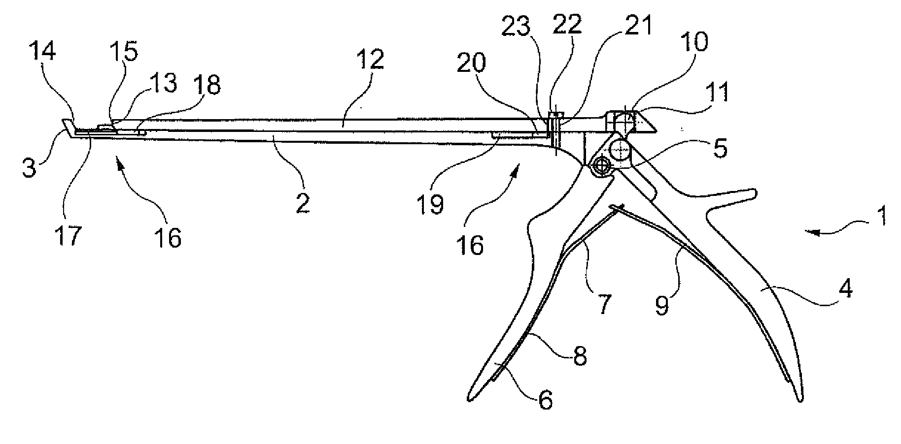
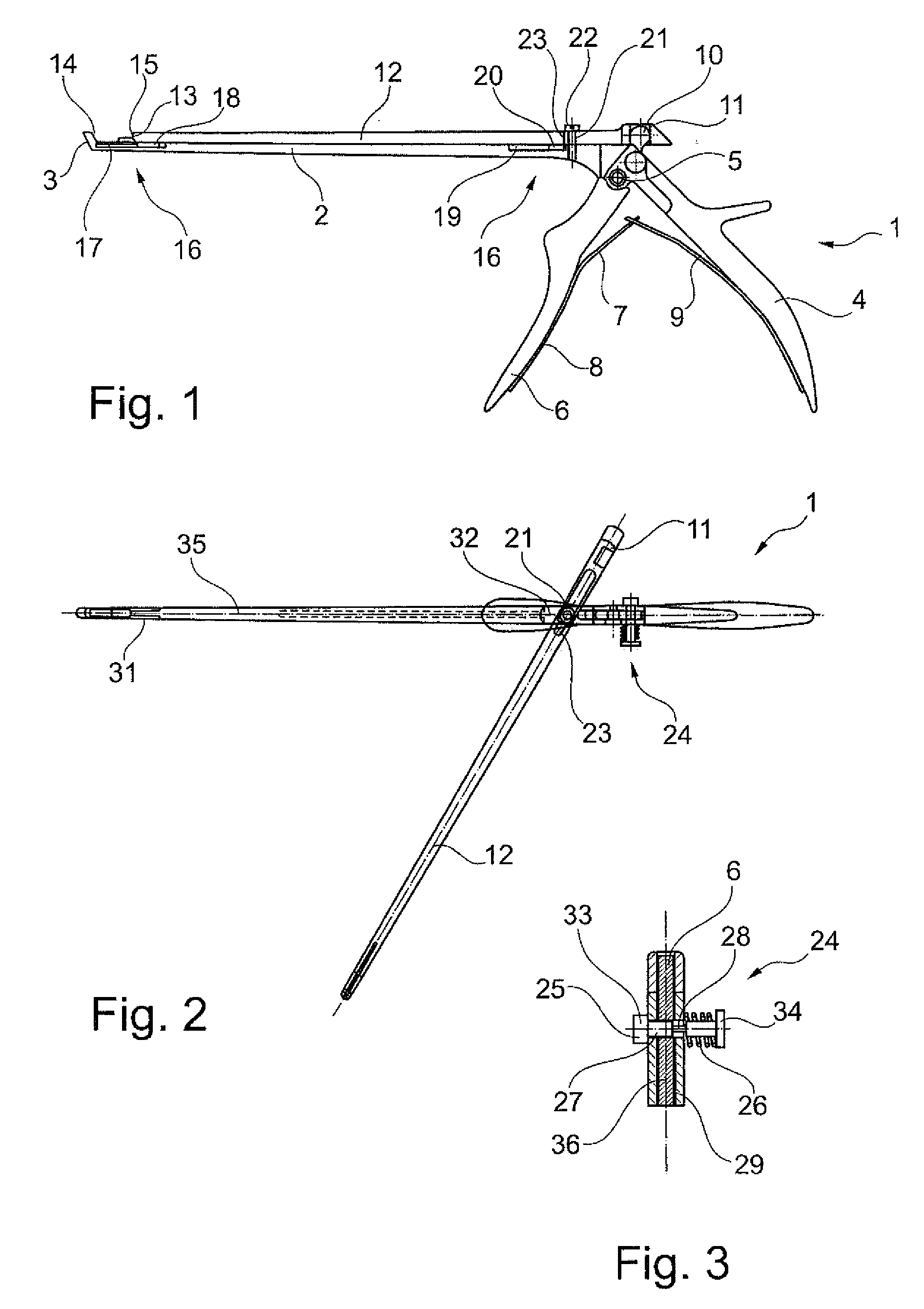
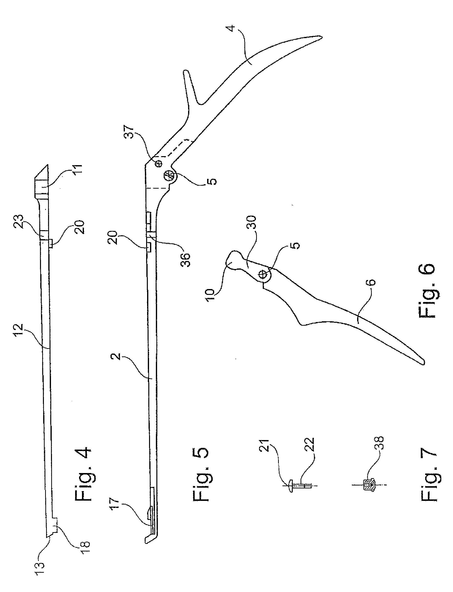
[0044]In FIGS. 1 and 2 a surgical instrument 1 is shown, serving as a punch. The surgical instrument 1 comprises an elongated shaft 2 with a distal (front) working end 3. A rear grip part 4 (gripping arm) is constructed in one piece with the shaft 2.

[0045]Relative to the fixed, proximal (rear) grip part 4, a distal (front) pivotable grip part 6 is pivotably arranged about a pivot axis 5 running transversely to the longitudinal extent of the shaft 2. Between the two grip parts 4, 6 an expander spring 7 is arranged in a manner known per se, which in the example embodiment shown is formed from two plate spring parts 9, wherein each plate spring part 8, 9 is screwed with a grip part 6, 4, and wherein the plate spring parts 8, 9 engage into each other with their free ends.

[0046]The pivotable (front) grip part 6 has an upper, approximately ball-head shaped end 10, which eng...


PUM


Abstract

A surgical instrument, in particular a laminectomy rongeur or a conchotome, with a shaft and with a one-piece sliding part, longitudinally displaceable relative to the shaft, with which for longitudinal displacement a grip part is associated which is pivotable about a pivot axis, wherein the sliding part is able to be transferred from a working position, in which the sliding part is guided longitudinally displaceably on the shaft in a guide, into a cleaning position, in which the sliding part is freed from the guide and is pivotable relative the shaft about a rotation axis oriented perpendicularly to the longitudinal extent of the shaft. The rotation axis is aligned perpendicularly to the pivot axis of the pivotable grip part.

Description

BACKGROUND OF THE INVENTION[0001]The invention relates to a surgical instrument, in particular a laminectomy rongeur or a conchotome.[0002]Such surgical instruments, also designated as sliding shaft instruments, are sufficiently known. Generally, laminectomy rongeurs are used as a punch for cutting through tissue, cartilage or bone and are used in particular in spinal operations. Sliding shaft instruments are distinguished by a sliding part, longitudinally displaceable relative to a fixed shaft, which sliding part is displaceable by actuation of a pivotable grip part (gripping arm) in the direction of the longitudinal extent of the shaft. Usually, the sliding part and the shaft cooperate here with distal working ends in the manner of a punch.[0003]A problem in known surgical instruments is mostly their only inadequate and complex cleanability. In order to be able to clean sliding shaft instruments in an improved manner, in particular in a region between the sliding part and the shaf...

Claims


Application Information

Patent Timeline
Patent Type & Authority Applications(United States)
IPC IPC(8): A61B17/00
CPCA61B17/1611A61B17/1671A61B2019/4868A61B17/1688A61B17/1679A61B2090/0813
Inventor HEINEMANN, NORBERT
Owner KARL LEIBINGER MEDIZINTECHNIK GMBH CO KG
Why Eureka
Try Eureka