Wireless transmission system, relay device, wireless sink device, and wireless source device

Inactive Publication Date: 2012-01-12
SHARP KK
View PDF20 Cites 22 Cited by
  • Summary
  • Abstract
  • Description
  • Claims
  • Application Information

AI Technical Summary

Benefits of technology

[0032]According to the present invention, when wireless AV transmission is performed, a plurality of the sink devices are operated in conjunction with each other with respect to each grou

Problems solved by technology

Since such a form of utilization through the multicast transmission is difficult in a wired AV transmission mode such as conventional

Method used


Image

  • Wireless transmission system, relay device, wireless sink device, and wireless source device
  • Wireless transmission system, relay device, wireless sink device, and wireless source device
  • Wireless transmission system, relay device, wireless sink device, and wireless source device

Examples


first embodiment

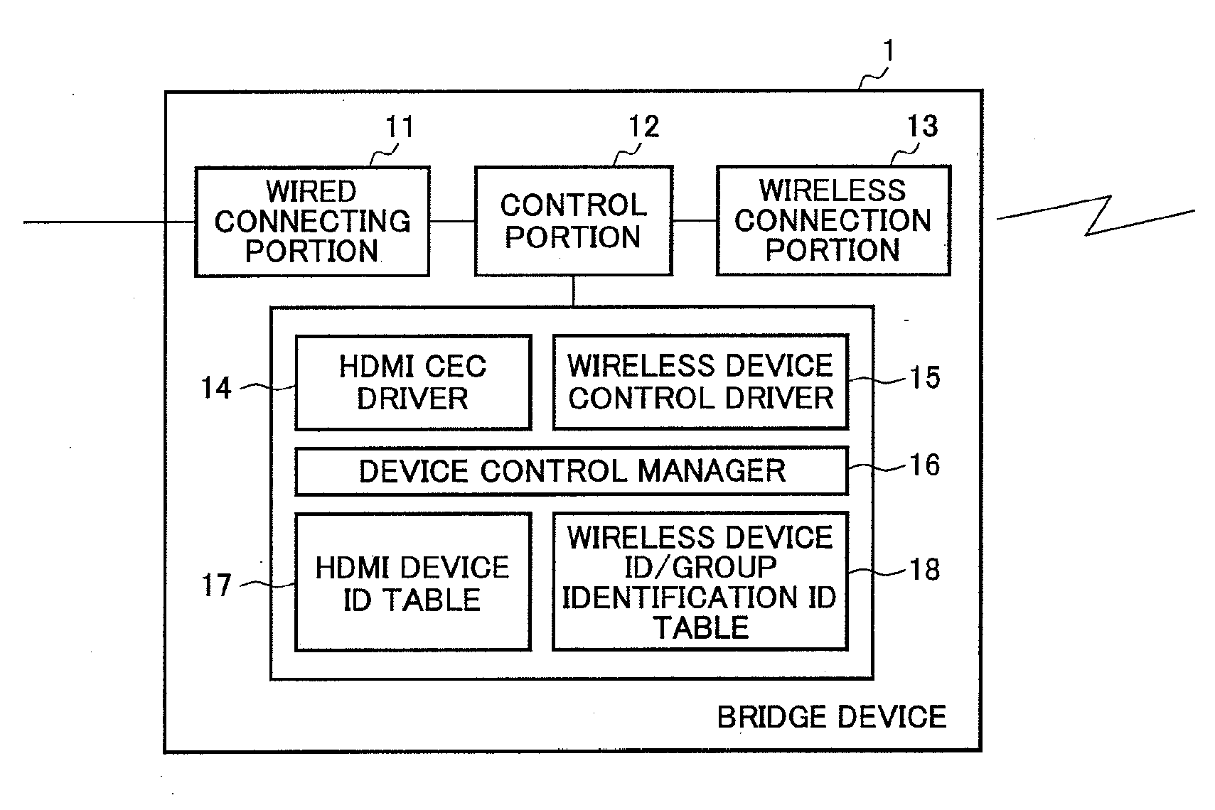
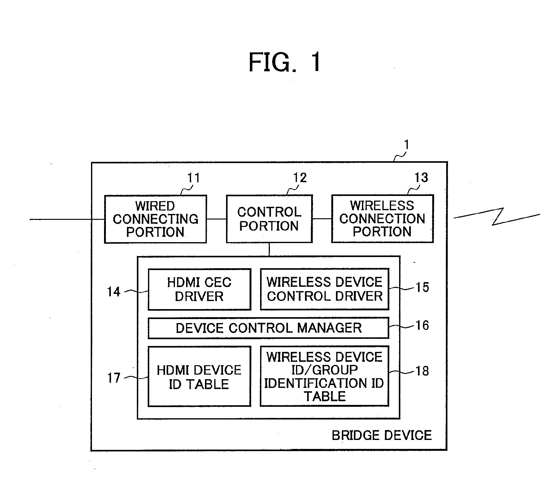
[0072]In this embodiment, as described above, the content transmitting apparatus is made up of the HDMI source device 2 and the bridge device 1 and all of a plurality of sink devices are made up of wireless sink devices (a television apparatus and one or more audio devices). In this case, the bridge device 1 is wirelessly connected to all the wireless sink devices.

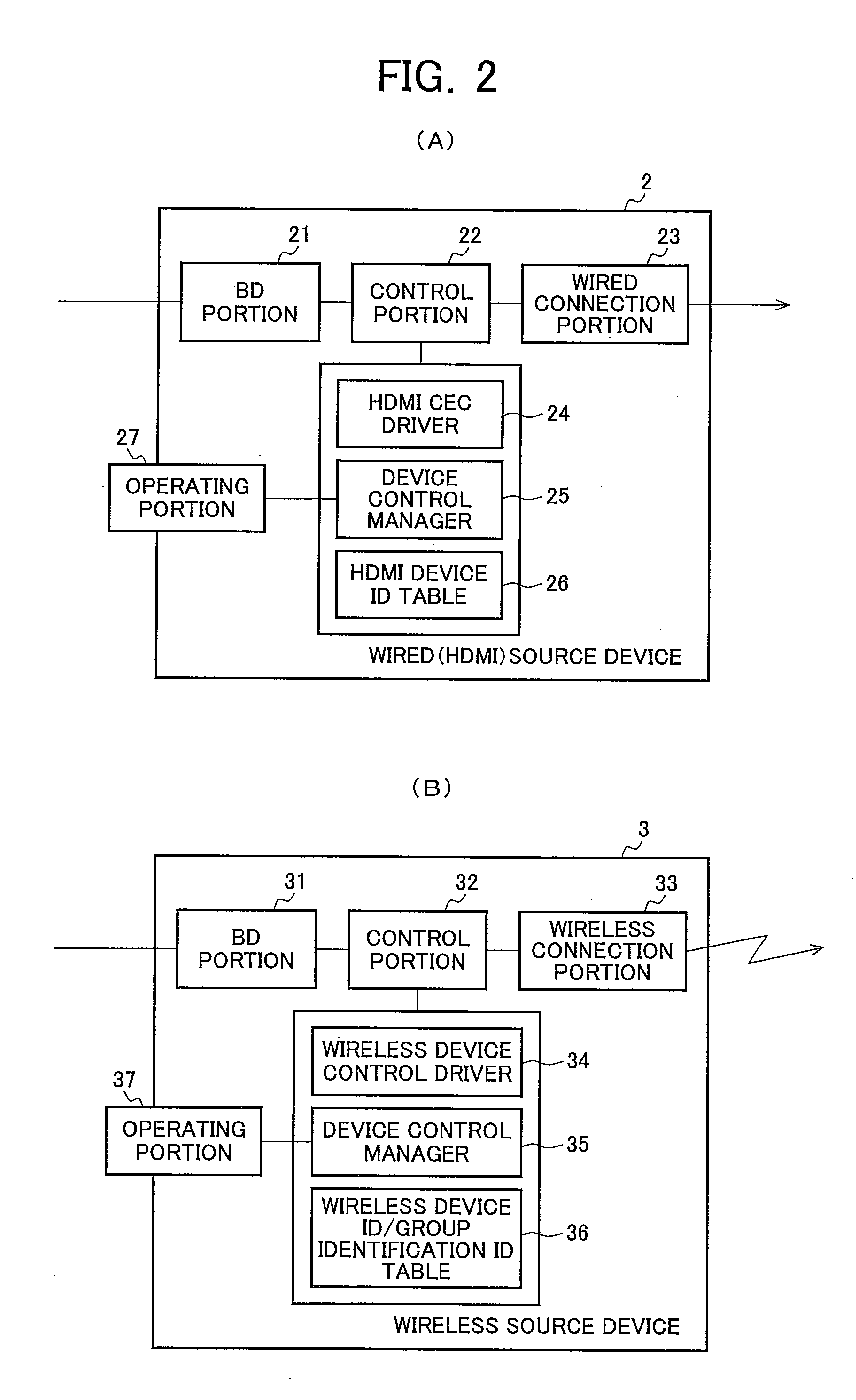
[0073]FIG. 4 is a diagram of an exemplary configuration of a wireless transmission system according to a first embodiment of the present invention. In this example, the HDMI source device 2 and the bridge device 1 are HDMI-connected and the bridge device 1 is wirelessly connected to a plurality of wireless sink devices. In FIG. 4, televisions are denoted by 5a and 5b and audios are denoted by 6a to 6c. The televisions 5a, 5b, and the audios 6a to 6c are wireless sink devices and the televisions 5a and 5b have an apparatus configuration depicted in FIG. 3(B). The audios 6a to 6c are, for example, audio output devices such a...

second embodiment

[0118]FIG. 10 is a diagram of an exemplary configuration of a wireless transmission system according to the second embodiment of the present invention. Bridge devices 1a and 1b have the apparatus configuration depicted in FIG. 1 and televisions 4a and 4b have the apparatus configuration depicted in FIG. 3(A). Audios 6d and 6e are, for example, audio output devices such as speakers and AV amplifiers and are made up of a wireless connecting portion, a control portion, a wireless device control driver, a device control manager, a wireless device ID / group identification ID table, and an audio output portion.

[0119]In this embodiment, as described above, the content transmitting apparatus is made up of the wireless source device 3, and the group A is made up of the bridge device 1a that is a wireless sink device, and the audio 6d and the television 4a that are HDMI-connected to the bridge device 1a. The group B is made up of the bridge device 1b that is a wireless sink device, the televis...


PUM


Abstract

A wireless transmission system is provided that can minimize the control command transmission amount by operating a plurality of sink devices in conjunction with each other with respect to each group when performing a wireless AV transmission. The wireless transmission system includes: a bridge device (1) which wireless-transmits an AV content; and a plurality of wireless sink devices (5, 6) which reproduce the wireless-transmitted AV content. The bridge device (1) has a group identification table which stores a group identifier for identifying a group formed by the wireless sink device (5, 6). The bridge device (1) adds a group identifier extracted from the group identification table to a control command for controlling the sink devices (5, 6) and wireless-transmits the control command having the group identifier. The wireless sink devices (5, 6) receive a control command wireless-transmitted from the bridge device (1) if a corresponding group identifier is added to the control command.

Description

TECHNICAL FIELD[0001]The present invention relates to a wireless transmission system, a relay device, a wireless sink device, and a wireless source device and more particularly to a wireless transmission system capable of grouping a plurality of sink devices and controlling operations of the sink devices with respect to each group, and a relay system, a wireless sink device, and a wireless source device making up the system.BACKGROUND ART[0002]A wireless network represented by a wireless LAN (local area network) is conventionally used for data transmission between devices such as personal computers (PC). Such a wireless network can be constructed so as to transmit data from an access point to devices through multicast transmission.[0003]For example, Patent Document 1 discloses a wireless transmission apparatus that wirelessly communicates with other communication stations within a wireless network. This wireless transmission apparatus includes a wireless processing means that transm...

Claims


Application Information

Patent Timeline
IPC IPC(8): H04N7/16H04L12/46H04N7/173H04N21/436
CPCH04L12/4625H04N21/43637H04N21/64753H04N21/43635H04N21/64746
Inventor EGUCHI, YOHICHITSUJI, KEISUKEOHMAE, RYOSUKEETOH, MASAYUKIIMANISHI, SEIJIKATOH, SHINICHIKINOSHITA, TAKUYA
Owner SHARP KK
Why Eureka
Try Eureka