Variable compression ratio apparatus

a compression ratio and variable technology, applied in mechanical equipment, machine/engine, engine controller, etc., can solve the problems of reducing the output power, reducing the distance from the bias ring to the center of the oil chamber, and limiting the ignition timing of spark ignition engines. to achieve the effect of stable and efficient variable compression ratio

Inactive Publication Date: 2012-01-19
HYUNDAI MOTOR CO LTD
View PDF5 Cites 5 Cited by
  • Summary
  • Abstract
  • Description
  • Claims
  • Application Information

AI Technical Summary

Benefits of technology

[0023]According to the exemplary embodiment of the present invention, since hydraulic pressure may be selectively released or supplied through the oil cha

Problems solved by technology

However, the spark ignition engines have a limit in increasing the ignition timing because the engines may be damaged by abnormal combustion when the ignition timing is increased at high compression ratio, which necessarily reduce the output power.
In order to achieve the variable compression ratio, an oil chamber is formed inside a bias ring disposed in a small portion of a connecting rod and the bias ring is eccentrically rotated by hydraulic pressure generated by supplying oil into the oil chamber

Method used


Image

  • Variable compression ratio apparatus
  • Variable compression ratio apparatus
  • Variable compression ratio apparatus

Examples


Embodiment Construction

[0043]Reference will now be made in detail to various embodiments of the present invention(s), examples of which are illustrated in the accompanying drawings and described below. While the invention(s) will be described in conjunction with exemplary embodiments, it will be understood that present description is not intended to limit the invention(s) to those exemplary embodiments. On the contrary, the invention(s) is / are intended to cover not only the exemplary embodiments, but also various alternatives, modifications, equivalents and other embodiments, which may be included within the spirit and scope of the invention as defined by the appended claims.

[0044]An exemplary embodiment of the present invention will hereinafter be described in detail with reference to the accompanying drawings.

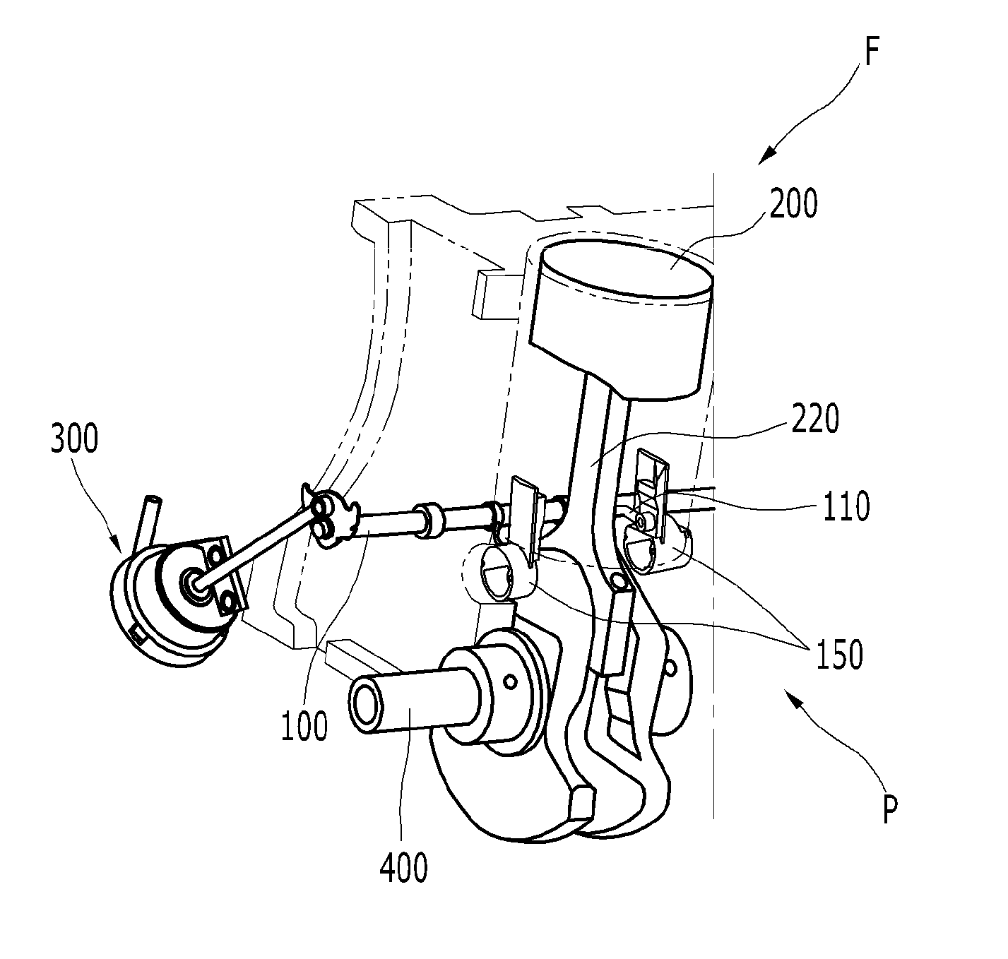
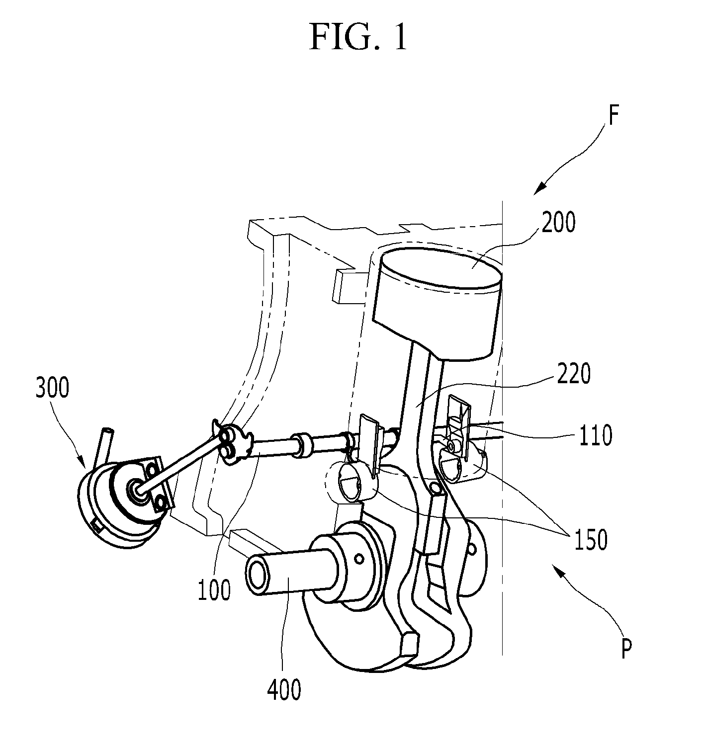
[0045]FIG. 1 is a perspective view showing a variable compression ratio apparatus according to an exemplary embodiment of the present invention.

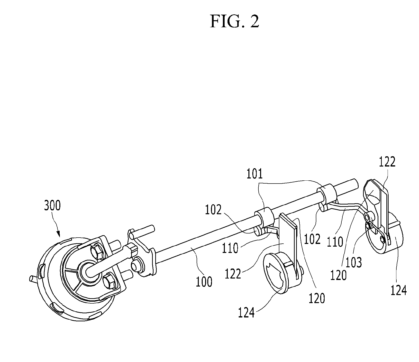
[0046]FIG. 2 is a perspective view showing a driving ...


PUM


Abstract

A variable compression ratio apparatus may include an external piston, a piston pin mounted in the external piston and a connecting rod, including an internal piston including a slot and sliding in an interior circumference of the external piston, wherein the piston pin passes through the internal piston and the external piston, a latching pin passing through the piston pin and selectively sliding therein, variable sliders disposed to selectively contact one of both ends of the latching pin, at both sides thereof to push the one of the both ends to the opposite side, and a support plate slidably supporting the variable sliders such that the variable sliders reciprocate perpendicular to length direction of the latching pin, wherein one end of a connecting arm selectively rotating may be connected to the variable slider and a sliding direction of the variable sliders may be controlled by rotation of the connecting arm.

Description

CROSS-REFERENCE TO RELATED APPLICATION[0001]The present application claims priority to Korean Patent Application No. 10-2010-0067412 filed in the Korean Intellectual Property Office on Jul. 13, 2010, the entire contents of which is incorporated herein for all purposes by this reference.BACKGROUND OF THE INVENTION[0002]1. Field of the Invention[0003]The present invention relates to a variable compression ratio apparatus. More particularly, the present invention relates to a variable compression ratio apparatus that changes compression ratio of gas mixture in a combustion chamber in accordance with operational conditions of an engine.[0004]2. Description of Related Art[0005]In general, thermal efficiency of heat engines increases when compression ratio is high and when igniting timing increases to a predetermined level in spark ignition engines. However, the spark ignition engines have a limit in increasing the ignition timing because the engines may be damaged by abnormal combustion ...

Claims


Application Information

Patent Timeline
IPC IPC(8): F02B75/04
CPCF02D15/04F02B75/044
Inventor LEE, JU HUNLEE, DONG SEOKYANG, JEI CHOONLEE, EUN HOCHOI, BYONG YOUNGKONG, JIN KOOKWOO, SOO HYUNG
Owner HYUNDAI MOTOR CO LTD
Why Eureka
Try Eureka