Disconnecting switch with earthing switch

a technology of earthing switch and disconnecting switch, which is applied in the direction of air-break switch, high-tension/heavy-dress switch, contacts, etc., can solve the problems of increasing the size of the entire gis, affecting the insulation characteristics of foreign objects, and reducing so as to reduce the size of the operating device, reduce the frictional force, and reduce the effect of frictional for

Active Publication Date: 2012-01-19
HITACHI LTD
View PDF10 Cites 21 Cited by
  • Summary
  • Abstract
  • Description
  • Claims
  • Application Information

AI Technical Summary

Benefits of technology

[0026]A 3-position switch according to the present invention is structured such that when a disconnecting switch-side and earthing switch-side moving contacts slide in a hollow disconnecting switch-side conductor and a hollow earthing switch-side conductor, respectively, each moving contact is linearly reciprocated by a two-hole lever via a curved link. This structure enables the reduction of the frictional force generated when a conventional single-hole lever is used as well as generated specifically at the initial motion. Furthermore, reduction of the frictional force leads to the decrease in the size of the operating device, which makes it possible to reduce the size of the entire apparatus.
[0027]Furthermore, since a curved link is directly connected to the two-hole lever to form a link mechanism portion, a complicated structure like conventional apparatuses is not necessary and a simple structure becomes possible. Such a simple structure enables the reduction of burden imposed when 3-position switches are manufactured. Furthermore, it is possible to reduce the generation of foreign objects including sliding powder coming from the link mechanism portion, thereby increasing reliability of the apparatus.
[0028]Furthermore, by mounting a sliding friction reducing member onto the inner circumferential surface of both the hollow disconnecting switch-side conductor and the hollow earthing switch-side conductor, it is possible to further reduce sliding friction that occurs when each moving contact travels.

Problems solved by technology

Therefore, there was a problem in that the tank length L1 of the sealed tank 101 becoming large, increasing the size of the entire GIS.
Therefore, there was a problem in that an operating device having a large drive output to operate the operating shaft 204 is necessary, causing the entire GIS to become large.
Furthermore, there was also a problem in that due to the friction between the moving contacts 207a, 207b and the cylindrical sliding surfaces of the conductors 203a, 203b, respectively, foreign objects that affect insulation characteristics could easily be produced.
However, there was a problem in that sliding powder was generated as the result of the rollers sliding on the cam groove.
Furthermore, another problem was that the structure was too complicated and it took time to produce.
However, the problem is the force component F13 that is generated in the direction perpendicular to the axis of the moving contact 207a.
However, the problem is the force component F23 that is generated in the direction perpendicular to the axis of the earthing switch-side moving contact 207b as previously stated.
Therefore, the conventional 3-position switch with a single-hole lever shown in FIG. 6 must use an operating device having a large operation force, which resulted in a problem that the size of the operating device increases.

Method used


Image

  • Disconnecting switch with earthing switch
  • Disconnecting switch with earthing switch
  • Disconnecting switch with earthing switch

Examples


embodiment 1

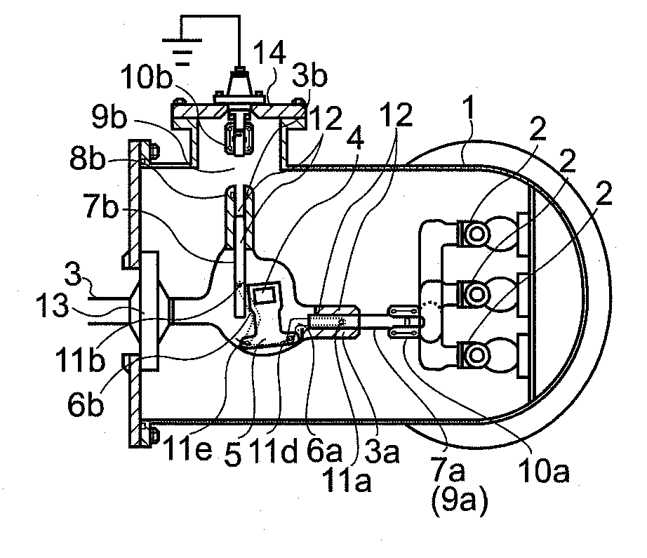
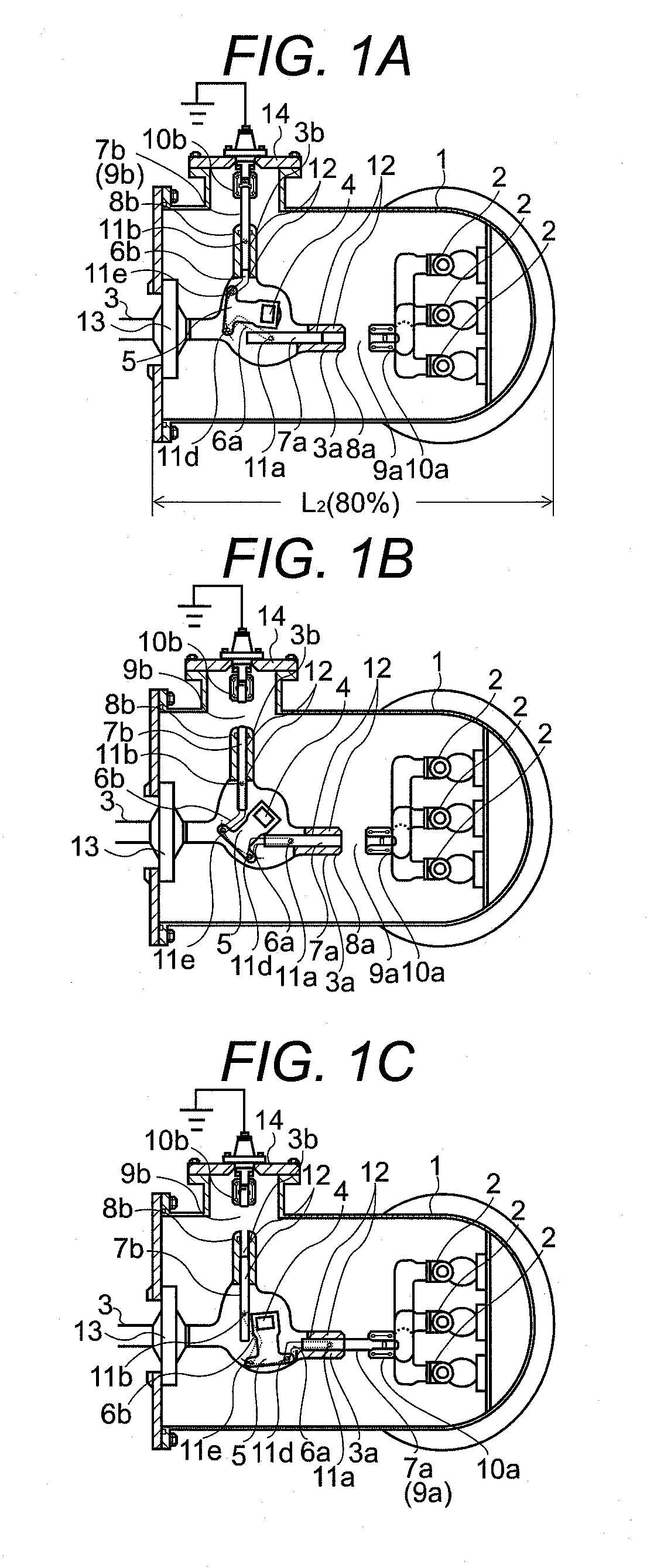
[0043]An embodiment of a 3-position switch according to the present invention is shown in FIGS. 1(A) through 1(C). In FIG. 1(A), the disconnecting switch portion 9a is in the open state and the earthing switch portion 9b is in the closed state. This state is hereafter referred to as a “grounding state”. In FIG. 1(B), both the disconnecting switch portion 9a and the earthing switch portion 9b are in the open state. This state is hereafter referred to as a “disconnecting state”. In FIG. 1(C), the disconnecting switch portion 9a is in the closed state and the earthing switch portion 9b is in the open state. This state is hereafter referred to as a “closed state”.

[0044]A three-phase main circuit conductor 2 is disposed in a gas-insulated sealed tank 1 so that the conductor extends in the direction shown in the drawing. This main circuit conductor 2 is provided with a disconnecting switch-side fixed contact 10a and is electrically connected to the contact. The main circuit conductor 2 of...


PUM


Abstract

Operating shaft 4 allows disconnecting switch-side and earthing switch-side moving contacts 7a and 7b to linearly reciprocate with the rotation of operating shaft 4. Operating shaft 4 has two-hole lever 5 allow an arc motion. Each one end of two curved links 6a and 6b is connected to two-hole lever 5 and the other end of two curved links 6a and 6b is respectively connected to the disconnecting switch-side moving contact or the earthing switch-side moving contact. When the two connecting points are axisymmetric with respect to the bisector, both the disconnecting switch and the earthing switch are in an open state; when two-hole lever 5 moves at a predetermined angle to the disconnecting switch-side, the disconnecting switch is in a closed state; and when two-hole lever 5 moves at a predetermined angle to the earthing switch-side, the earthing switch is in a closed state.

Description

TECHNICAL FIELD[0001]The present invention relates to a disconnecting switch and earthing switch has a 3-position switch portion which is a disconnecting switch with earthing switch (hereafter, referred to as a “3-position switch”), and specifically to a 3-position switch that has a simple structure and can reduce the size of the entire apparatus.BACKGROUND ART[0002]A gas-insulated switchgear (hereafter, referred to as a “GIS”) has devices, such as a breaker, disconnecting switch, earthing switch and the like. The GIS often uses a 3-position switch wherein an earthing switch and a disconnecting switch are united in a sealed tank.[0003]FIG. 5 shows the outline of the 3-position switch that has been commonly used. The 3-position switch is constructed such that in an sealed tank 101 having a tank length of L1, there are provided three-phase main circuit conductors 102 extending in the direction shown in the drawing and a main circuit conductor 103 disposed so that the extended axes the...

Claims


Application Information

Patent Timeline
Patent Type & Authority Applications(United States)
IPC IPC(8): H01H9/26
CPCH01H1/385H01H3/46H01H33/42H01H31/32H01H33/122H01H31/003
Inventor SHIN, TAEYONGYAGINUMA, KYUJI
Owner HITACHI LTD
Why Eureka
Try Eureka