Welding parameter control

a welding parameter and control technology, applied in the field of motion detection system for adjusting a, can solve the problems of affecting the welding operation, and affecting the welding operation etc., and affecting the operation of the welding operator. , the location of the welding application may be too distant or remote for the operator to adjust the operating parameters

Active Publication Date: 2012-01-19
ILLINOIS TOOL WORKS INC
View PDF23 Cites 78 Cited by
  • Summary
  • Abstract
  • Description
  • Claims
  • Application Information

AI Technical Summary

Problems solved by technology

For certain welding applications, the power supplies, which may weigh over 80 pounds, are too large or cumbersome to position proximate to the welding operation.
For example, the location of a weld may be elevated, confined, restricted, or otherwise difficult to access.
In other words, the location of a

Method used


Image

  • Welding parameter control
  • Welding parameter control
  • Welding parameter control

Examples


Embodiment Construction

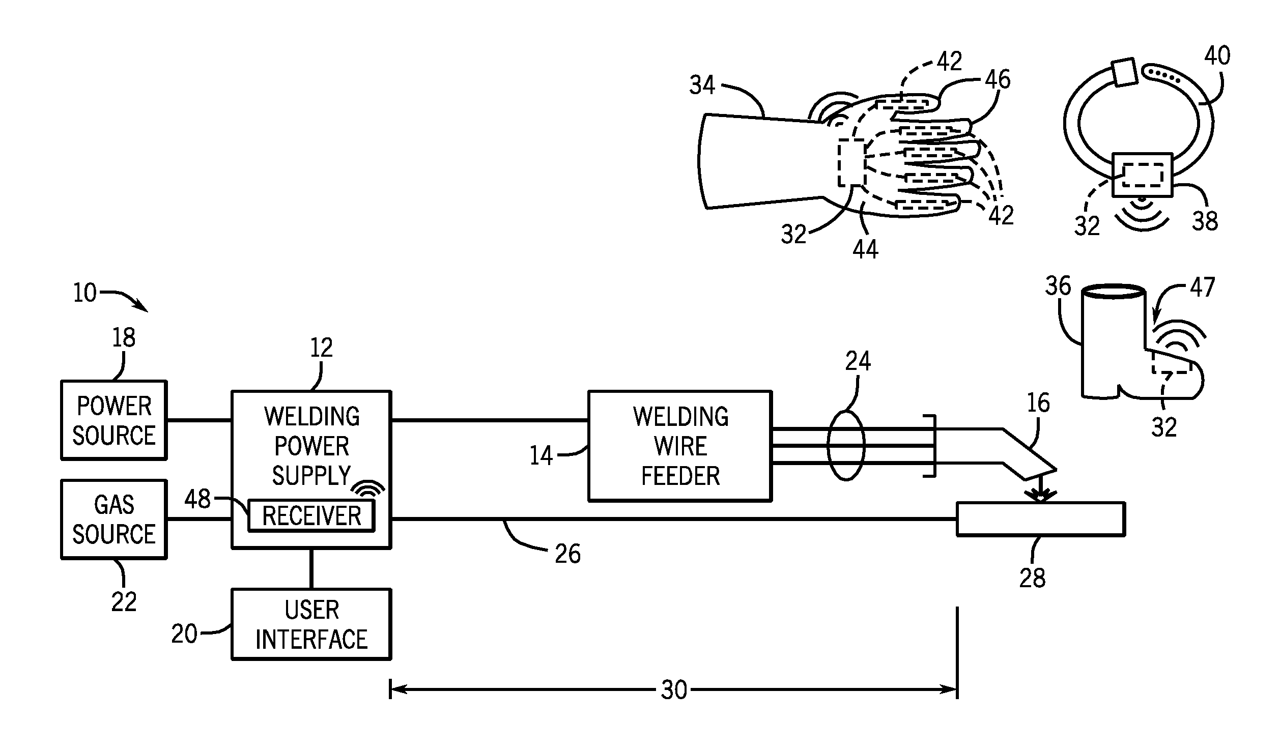
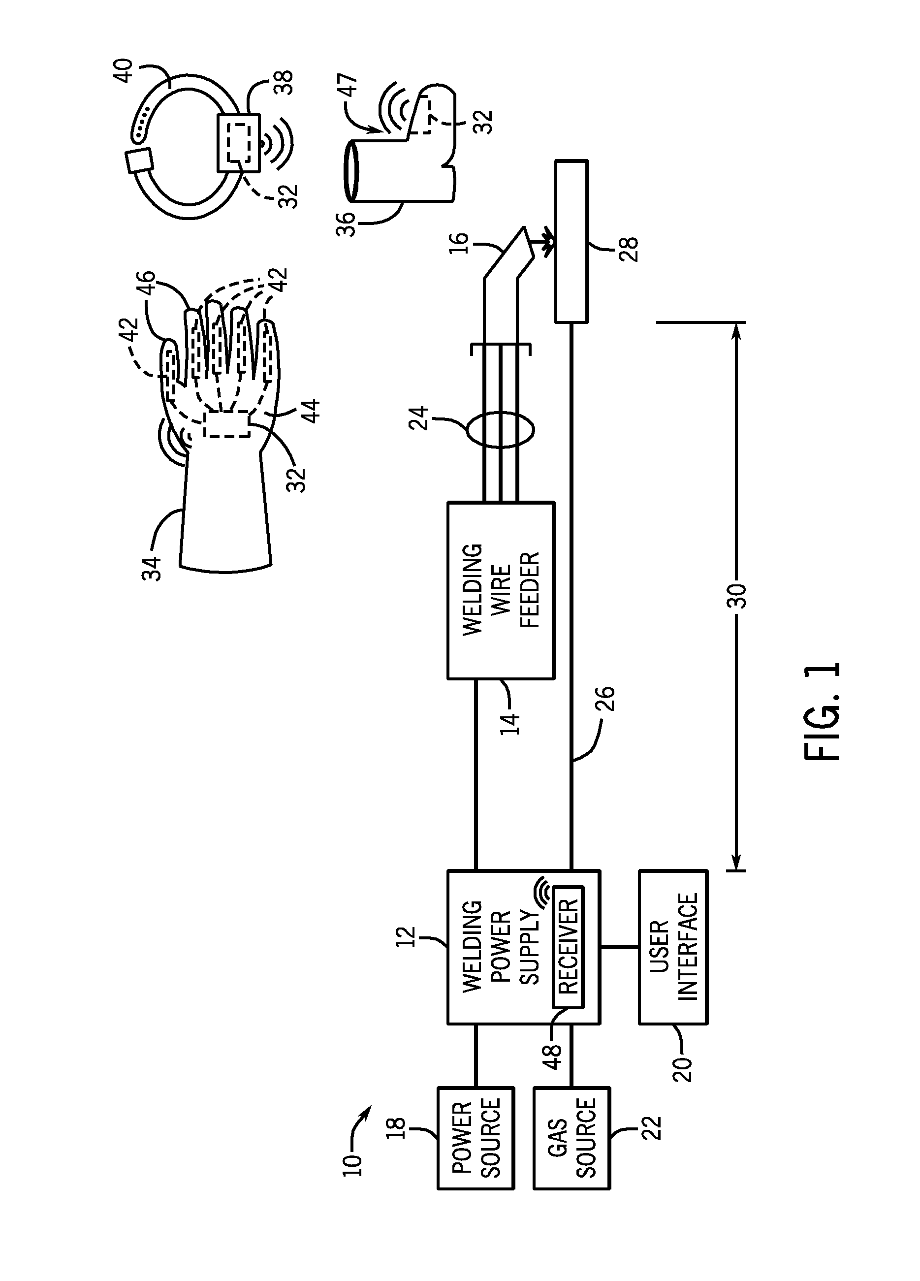
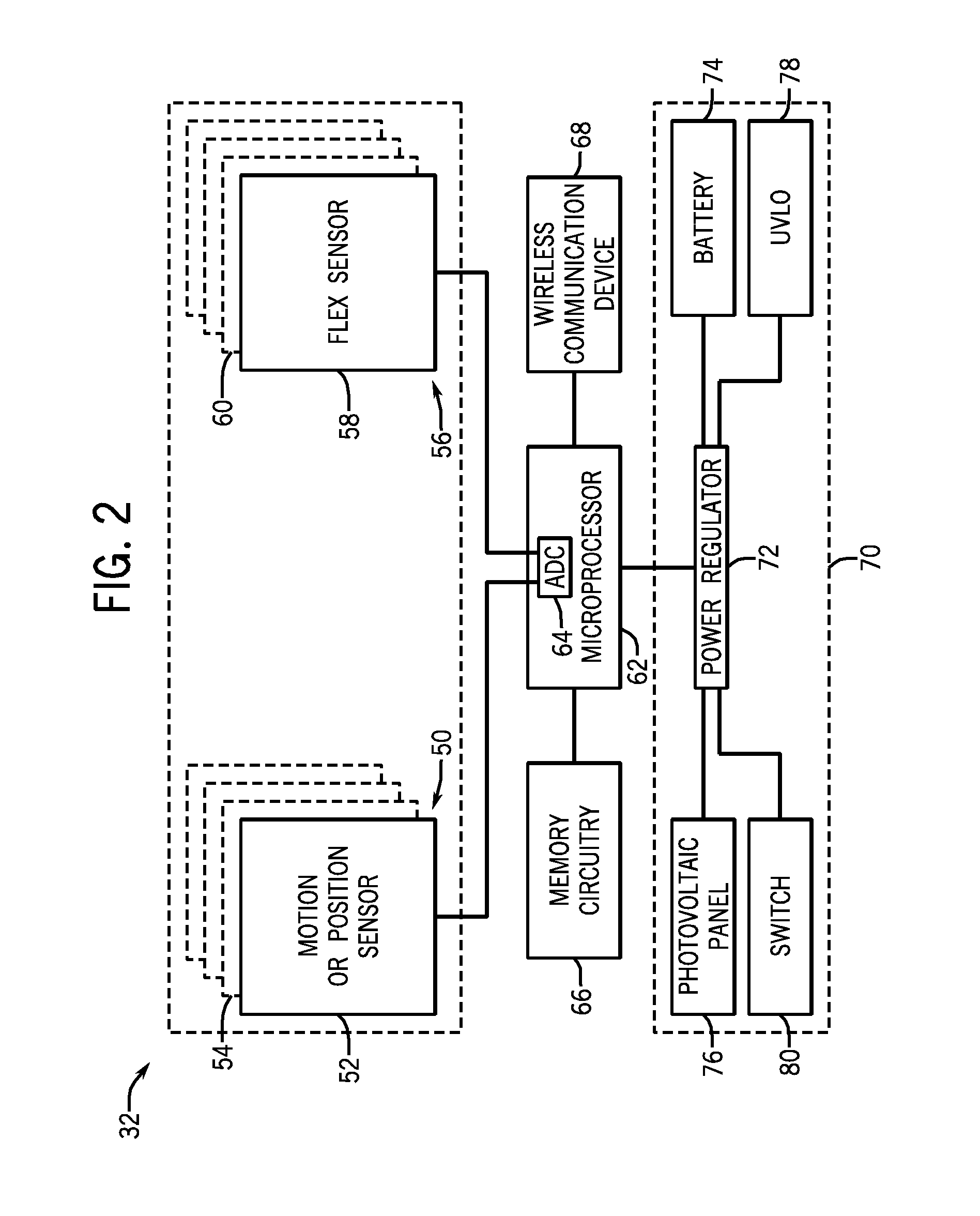
[0013]The present disclosure describes exemplary embodiments of a wireless sensor module for controlling an operating parameter of a welding power supply or welding machine. The wireless sensor module is worn by a welding operator and is configured to detect defined motions or positions of the welding operator. More specifically, the wireless sensor module includes one or more motion sensors, position sensors, and / or flex sensors configured to detect or measure particular movements or positions of the welding operator. For example, the wireless sensor module may be integrated with a glove or piece of footwear such as a boot or shoe. Alternatively, the wireless sensor module may be a stand-alone module that is strapped to an appendage, such as an arm or a leg, of the welding operator.

[0014]As mentioned above, the sensors of the wireless sensor module are configured to detect particular motions and / or positions of the welding operator. Based on the motions and / or positions of the weld...


PUM

PropertyMeasurementUnit
Poweraaaaaaaaaa
Currentaaaaaaaaaa
Electric potential / voltageaaaaaaaaaa

Abstract

In certain embodiments, a wireless sensor module includes a motion or position sensor configured to detect a defined motion or position of a welding operator. The wireless sensor module also includes memory circuitry configured to store the defined motion or position and an adjustment of an operating parameter of a welding system which corresponds to the defined motion or position. A processor of the wireless sensor module is coupled to the motion or position sensor and the memory circuitry, where the processor is configured to retrieve the adjustment of the operating parameter from the memory circuitry upon detection of the defined motion or position by the motion or position sensor. The wireless senor module further includes a wireless communication device coupled to the processor and configured to transmit the adjustment of the operating parameter to the welding system.

Description

CROSS REFERENCE TO RELATED APPLICATIONS[0001]This application is a Non-Provisional Patent Application of U.S. Provisional Patent Application No. 61 / 364,274 entitled “Motion Control Welding Gloves”, filed Jul. 14, 2010, which is herein incorporated by reference.BACKGROUND[0002]The invention relates generally to welding systems, and, more particularly, to a motion detecting system for adjusting a welding parameter.[0003]Welding systems generally include power supplies configured to provide an electric current for use in a welding operation. The power supplies include a user interface allowing an operator to adjust one or more operating parameters of the power supply. For example, the user interface may enable the operator to select or adjust voltage output, current output, welding wire size, welding process, and so forth. For certain welding applications, the power supplies, which may weigh over 80 pounds, are too large or cumbersome to position proximate to the welding operation. For...

Claims


Application Information

Patent Timeline
IPC IPC(8): B23K11/24
CPCB23K9/0956B23K9/321B23K9/1087
Inventor WIRYADINATA, INDRA BUDIMAN
Owner ILLINOIS TOOL WORKS INC
Why Eureka
Try Eureka