Flat-article feed device and a postal sorting machine

a feed device and flat-article technology, applied in the direction of article feeders, pile separation, pile separation, etc., can solve the problems of difficult to separate mailpieces, less fragile mailpieces being damaged, and devices that cannot enable the phenomenon of multiple feeds to be overcome reliably, so as to improve the quality of unstacking

Inactive Publication Date: 2012-01-19
SOLYSTIC
View PDF4 Cites 23 Cited by
  • Summary
  • Abstract
  • Description
  • Claims
  • Application Information

AI Technical Summary

Benefits of technology

[0009]An object of the invention is to propose a flat-article feed device for feeding flat articles, in particular mailpieces, that makes it possible to achieve a further improvement in the quality of unstacking by overcoming phenomena of multiple feeds to an even better extent.
[0011]The basic idea of the invention is thus to separate the unstacking function from the transfer function by offsetting the unstacking means in itself from the supply magazine in said second transfer direction by a distance sufficiently long to reduce phenomena of multiple feeds. The space left empty between the supply magazine and the unstacker means thus makes it possible to install retaining means facing the upstream end of the unstacker means. The retaining means are therefore adjacent to the supply magazine. At this location of the retaining means, the mailpieces have not yet reached their nominal conveying speed in the conveyor, and they are being accelerated, so that the action of the retaining means does less damage to the mailpieces than in the state of the prior art, and is more effective. In addition, this sufficiently long intermediate zone between the supply magazine and the unstacker means constitutes a corridor in which the unstacked mailpieces are placed one after another in the second transfer direction before they are presented facing the unstacker means. In a particular embodiment of the invention, said unstacker means comprise a perforated belt that is motor-driven so as to move in said second transfer direction, and at least one suction nozzle that is designed to exert on the flat article being unstacked an attraction force oriented substantially perpendicularly to said second transfer direction in order to press it against the motor-driven perforated belt, and the retaining means exert on the flat article being unstacked a retaining force that opposes and that is substantially in alignment with said attraction force. These two mutually “opposing” and “aligned” forces are thus forces acting in opposition one against the other in alignment on either side of the surface of the mailpiece, thereby tending to prevent the mailpiece from being damaged by shear forces.
[0012]The retaining means are preferably arranged to exert said retaining force in discontinuous manner, thereby reinforcing the effectiveness of the unstacking.

Problems solved by technology

In that known feed device, the separator means and the unstacker means are constituted by the same means, and the mailpiece being unstacked is subjected to the pressure from the remainder of the stack of mailpieces present in the supply magazine, and that can be a cause of jams and of multiple feeds.
Unfortunately, downstream from the unstacker means, the mailpieces are already being driven at high speed, i.e. at the conveying speed at which the mailpieces are conveyed in the conveyor, and that makes it difficult to separate mailpieces that are stuck together in multiple-feed bunches, and can give rise to the more fragile of the mailpieces being damaged due to shear forces being exerted on such mailpieces.
However, those devices do not enable phenomena of multiple feeds to be overcome reliably.

Method used


Image

  • Flat-article feed device and a postal sorting machine
  • Flat-article feed device and a postal sorting machine

Examples


Embodiment Construction

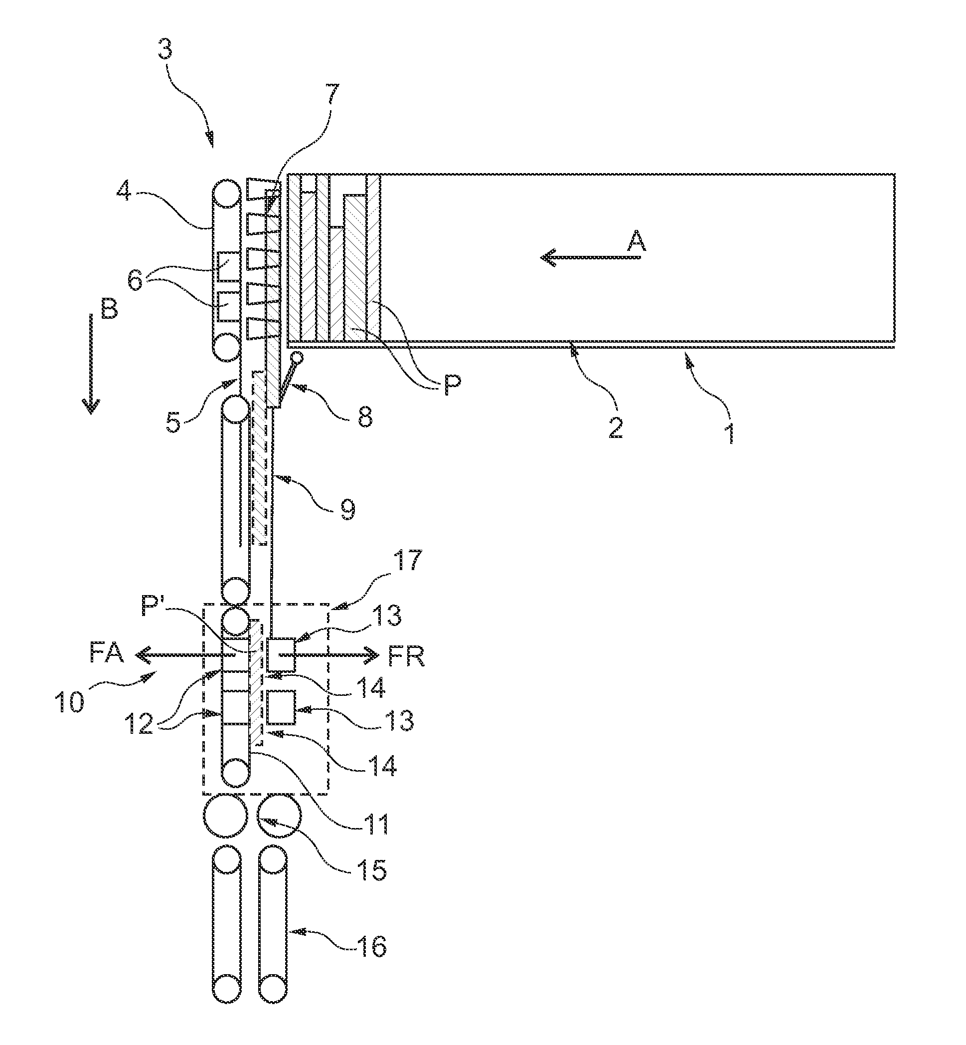
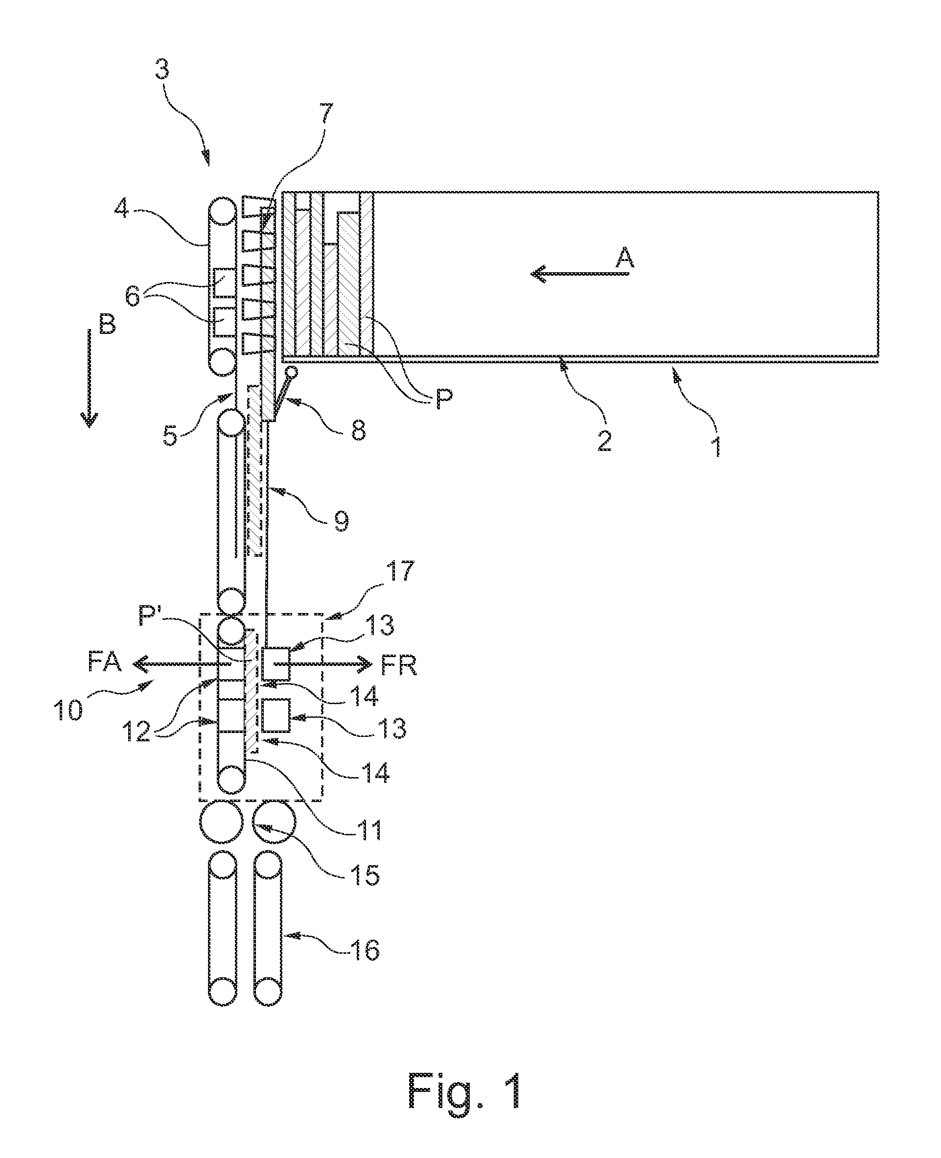
[0021]FIG. 1 is a highly diagrammatic view of a mailpiece feed device of the invention that is designed more particularly for a postal sorting machine.

[0022]This feed device includes a supply magazine 1 in which mailpieces P aligned against a jogger edge 2 are stored in a stack on edge with a view to being unstacked. The mailpieces P are shown in FIG. 1 on edge and seen from above.

[0023]The floor of the magazine 1 on which the mailpieces rest on edge may be a motor-driven belt that moves the stack of mailpieces in a transfer direction A towards the front of the supply magazine. A movable paddle (not shown) that is movable in the direction A and that may or may not be motor-driven, may also be provided to hold the back of the stack.

[0024]At the front of the supply magazine, transfer means 3 are provided and they thus face the front of the stack of mailpieces. The function of the transfer means is to separate the leading mailpiece in the stack from the remainder of the stack, and to m...


PUM

PropertyMeasurementUnit
speedaaaaaaaaaa
thicknessaaaaaaaaaa
thicknessaaaaaaaaaa

Abstract

The invention relates to a flat-article feed device, comprising a supply magazine (1) in which flat articles are moved in a stack on edge in a first transfer direction (A), separator means (3) for separating the leading flat article of the stack from the remainder of the stack and for driving it in a second transfer direction (B) that is substantially perpendicular to the first transfer direction, unstacker means (10) that take a flat article that is being unstacked and bring it in said second transfer direction (B) to the inlet of a conveyor, and retaining means (13) that exert a retaining force that opposes movement of the flat article towards the conveyor, said unstacker means being offset from said separator means by a distance not less than the maximum length of a flat article, and said retaining means being provided facing the unstacker means. The invention also relates to a postal sorting machine including such a feed device.

Description

TECHNICAL FIELD[0001]The invention relates to a flat-article feed device, comprising a supply magazine in which flat articles are moved in a stack on edge in a first transfer direction, separator means for separating the leading flat article of the stack from the remainder of the stack and for driving it in a second transfer direction that is substantially perpendicular to the first transfer direction, unstacker means that take a flat article that is being unstacked and that is separated from the stack and bring it in said second transfer direction to an inlet of a conveyor, and retaining means that exert a retaining force on the flat article being unstacked, which force opposes movement of said article towards the conveyor. The invention also relates to a postal sorting machine including such a feed device.PRIOR ART[0002]In the meaning of the invention, a “flat article” is, particularly but not exclusively, a mailpiece. Mailpieces that are suitable for being unstacked by means of t...

Claims


Application Information

Patent Timeline
Patent Type & Authority Applications(United States)
IPC IPC(8): B65H5/00B65H3/00
CPCB65H3/124B65H3/46B65H3/52B65H2701/1916B65H2301/321B65H2406/31B65H2406/351B65H2301/22
Inventor SAMAIN, STEPHANEDAUVERGNE, MICKAELAMBROISE, STEPHANE
Owner SOLYSTIC
Why Eureka
Try Eureka